Connecting a pc/plc link unit, Connection diagram environment settings parameters – KEYENCE LK-G5000 Series User Manual
Page 21
21
1
(V)
(A)
0V
(V)
(A)
0V
LK
-G
50
00
1
(V)
(A)
0V
(V)
(A)
0V
LK
-G
50
00
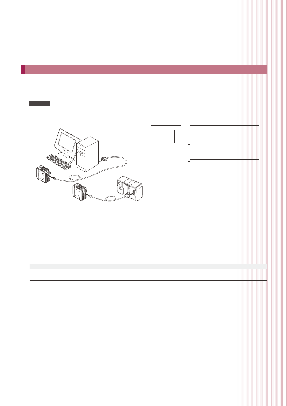
Connecting a PC/PLC link unit
The connection requires the OP-96368 dedicated cable (2.5 m straight cable) and either
the OP-26401 (D-sub 9-pin) or OP-96369 (D-sub 25-pin) conversion adapter.
LK-G side
RD (RXD)
(5)
SG (GND)
(4)
SD (TXD)
(3)
Change the following parameters on the PC or PLC link unit to be connected.
Item
Setting value
Remark
Baud rate
9600/19200/38400/57600/115200
Set the appropriate parameter according to the external
device to be connected.
Parity check
None/even/odd
* Also refer to user's manual for the PC or PLC link unit before starting connection.
PC
PLC link unit
Be sure to read “Precautions on wiring”(pg.7) of the user's manual before starting wiring.
NOTE
Connection diagram
Environment settings parameters
PC side
OP-96369
OP-26401
Signal name
(3)
(2)
RD (RXD)
(7)
(5)
SG (GND)
(2)
(3)
SD (TXD)
(4)
(7)
RS (RTS)
(5)
(8)
CS (CTS)
(6)
(6)
DR (DSR)
(8)
(1)
CD (DCD)
(20)
(4)
ER (DTR)