Ok ng, Thickness measurement setting methods, Preparation and overview – KEYENCE LK-G5000 Series User Manual
Page 12
12
Thickness Measurement Setting Methods
When two sensor heads are connected to measure thickness between the two sensor heads, the setting method is as follows.
With measurement between two sensor heads, it is possible to minimise the influence of vertical vibration.
Preparation and Overview
Required Components
No. of units
LK-G5000 Series controller
1
LK-G5000 Series sensor head
2
LK-G5000 Series head cable
2
LK-Navigator 2 configuration software
1
24 V power source
1
1. Sensor head mounting bracket
2. Adjusting the optical axis.
In order to perform measurement between two sensor heads, mount
the sensor heads as seen in the figure on the right. Once the target
has been inserted, mount the sensor head so that the surface of the
target comes to the standard distance for each head.
The optical axis for two sensor heads is adjusted to form a single
straight line. Adjust the optical axis so that the relative spot position
does not deviate even if the target is moved up and down.
Reverse-C-shaped single-body jig
OK
NG
As seen in the image on the right, a reverse-C-shaped single body jig can
reduce the influence of vibration in the mounting bracket.
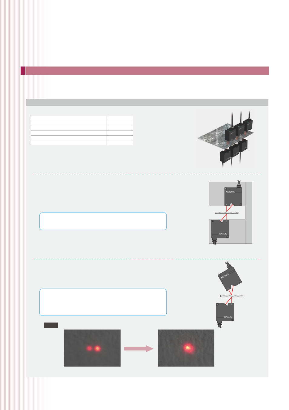
Use a thin, white coloured plastic or piece of paper as a setup tool. These
types of materials will allow the user to see both the top and bottom spot
simultaneously. Sensor head position should be adjusted so that the beam
spots appear to overlap at all points in the measurement range.
The laser spots are slightly misaligned
Modify target installation so that the centres of
the laser spots overlap to form a single
The laser spots are
overlapping
Check that the top and bottom spots are properly overlapped even if the target is moved up and down.
USEFUL TIP
USEFUL TIP
Note