Models that require an neutral density filter – KEYENCE LK-G5000 Series User Manual
Page 15
15
Setting methods for measuring the thickness of transparent objects
Preparation and Overview
Settings and Procedures
The following settings should be used as a default.
The setting methods that are used when measuring the thickness of transparent objects with the LK-G5000 are as follows. With
the LK-G5000, position data for the top and bottom surface are obtained as the detection surface, so it is possible to measure the
thickness of transparent objects from one side.
Required Components
No. of units
LK-G5000 Series controller
1
LK-G5000 Series sensor head
1
LK-G5000 Series head cable
1
LK-Navigator 2 configuration software
1
24 V power source
1
Models that require an neutral density filter
LK-H080/082/085/087 ➔ Mount the LK-F3
LK-H150/152/155/157 ➔ Mount the LK-F2
An neutral density filter must be mounted with the following models.
Mount the sensor head at an angle that is half of angle a, which is listed in the schematics for the LK-G5000.
* Mounting at an angle is not required for the LK-H008/LK-H008W.
Neutral density
Filter
LK-F3
LK-F2
a
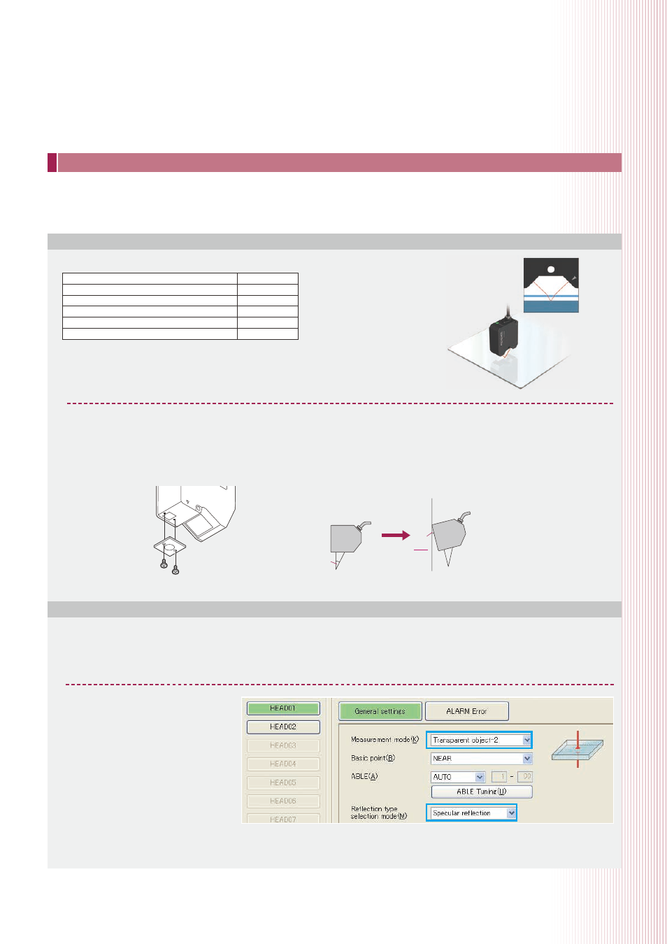
1. Set the measurement mode for head 01 to “Transparent object-2” and set the installation
mode to “Specular reflection”.
Once the measurement mode
is set to Transparent object-2,
ABLE adjustment will take effect
individually for the top and bottom
surfaces of transparent objects.
This will allow stable position
measurement for both surfaces.
* ABLE adjustment: A function that senses
the top surface of the measurement target
to adjust to the optimal amount of laser
light.
Angle
a
2