KEYENCE LK-G5000 Series User Manual
Page 16
16
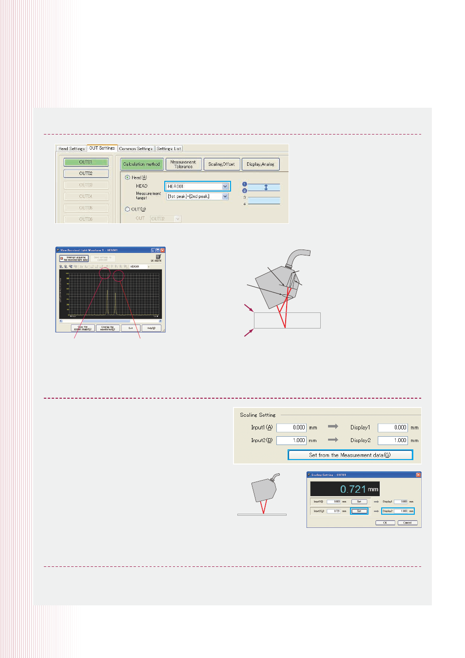
2. For the calculation method for OUT1, set the measurement target to “[1st peak] – [2nd peak]”.
3. Measurement value scaling
4. Click the button for “Send settings to controller”. (pg. 3 of this guide)
Waveform for received light
from the top surface
Waveform for received light
from the bottom surface
Displaying received light waveforms
Received light waveform when measuring transparent glass
Top surface (1st peak)
Bottom surface (2nd peak)
Master workpiece
(For example, a thickness of
0.1 mm)
Sensor head
Light-receiving
lens
Top surface
reflected light
Bottom surface
reflected light
Transparent glass
Light-receiving
element
(CMOS)
(1) Click “OUT1 Scaling, Offset”.
(2) Click “Set from measured data” in scaling settings.
(3) Measure the master workpiece.
(4) Click “Set” for input value 2.
(5) Enter the thickness of the master workpiece for
Display2. For example, if the thickness of the master
workpiece is 1.0 mm, enter “1.000” for Display2.
(6) Click [OK] and then click “Send settings to controller”.
Click the “Measurement value acquisition start” button and Measurement Value Acquisition/Display will appear.