Tips for convenient functions, Automatic setup of range criteria values, Preset – KEYENCE GT-70A Series User Manual
Page 6: Bank switching, Calculation with expansion unit, Keylock
6
GT-M-E
Tips for Convenient Functions
■
Automatic setup of range criteria values
This function automatically sets an upper limit value (HIGH setting
value) and a lower limit value (LOW setting value).
For master workpieces, set by "tolerance tuning"; and for actual
works (good or defective), set by "two-point tuning".
Tolerance tuning
Tolerance tuning is disabled when "------", "- FFFF" or
"FFFF" is displayed.
1
When in the main display, press the
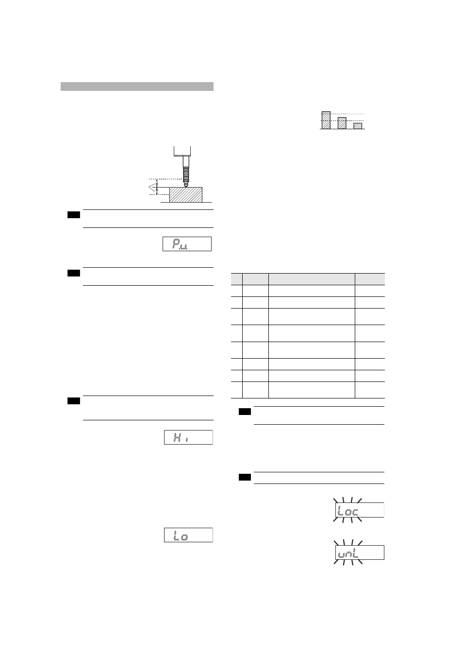
left/right Arrow buttons until the P.V.
value display appears, then perform
detection of the master workpiece.
Tolerance tuning is enabled only when in the P.V. value
display.
2
Press the [SET] button while the master workpiece is being
detected to capture the detected value.
3
Press the upper/bottom Arrow buttons to enter a tolerance
tuning setting range.
4
Press the [SET] button to fix the tolerance tuning setting range.
After [SEt] blinks several times on the digital LED display of the
amplifier, the P.V. value display automatically appears.
Tolerance tuning is completed.
Two-point tuning
This is the method of setting the median values of the detected
good and/or defective workpieces as a range when the good
workpiece and HIGH/LOW defective workpieces are available.
Two-point tuning is disabled when "------" is displayed
as a P.V. value. When "- FFFF" or "FFFF" is displayed,
setting cannot be done accurately.
1
When in the main display, press the left/
right Arrow buttons until the HIGH
setting value display appears.
2
Detect the good workpiece and press the [SET] button to
capture the detected value.
"SEt" and the detected value blink alternately, and the value of the
good workpiece is fixed.
3
Detect the HIGH defective workpiece and press the [SET]
button to capture the detected value.
The median value of this detected value and the one captured in
step 2 blinks.
HIGH setting value is fixed.
4
Press the right Arrow button until the
LOW setting value display of the main
display appears.
5
Detect the good workpiece again and press the [SET] button to
capture the detected value.
6
Detect the LOW defective workpiece and press the [SET]
button to capture the detected value.
The median value of this detected value
and the one captured in step 5 blinks.
LOW setting value is fixed.
Two-point tuning is completed.
Press the left/right Arrow buttons
to return to the P.V. value display.
■
Preset
This function displays the value obtained by adding or subtracting a
preset value to or from the detected value.
By using this function and the zero point correction function together,
you can set an arbitrary value as a reference point of the work.
■
Bank switching
By using the bank switching, you can register up to four patterns of
the HIGH setting value, LOW setting value and preset value,
respectively.
The bank switching is useful when there are multiple detection
targets since the pre-registered settings (four patterns) can be
easily switched.
■
Calculation with expansion unit
The GT-70A Series can calculate various values using the detected values
of multiple detection points such as the maximum value or the minimum
value when an expansion unit(s) is added (up to nine units).
Refer to pages 2 to 3 of this manual for details about how to add an
expansion unit.
The outline of the calculation function is shown below.
The calculation function is selectable only on a main
unit with one or more expansion units added.
■
Keylock
The keylock allows you to avoid erroneous button operation during
detection.
When the keylock is active, setup operations other than changing
the display are disabled.
The keylock setup can be set on the main display only.
● Set the keylock
When in the main display, while pressing
the [MODE] button, press the upper
Arrow button for at least two seconds.
The keylock display will appear for several
seconds and then change to the main display.
● Cancel the keylock
When in the main display, while pressing
the [MODE] button, press the upper
Arrow button for at least two seconds.
The keylock cancel display will appear for several
seconds and then change to the main display.
HIGH setting value
LOW setting value
Tolerance tuning setting range
This is a method for setting a range based on
the detection value of a master workpiece
when the master workpiece is available.
Note
Note
Note
HIGH setting value display
LOW setting value display
No.
Calculation
function
Description
Number of units
connected
C1
Max. value
Displays the maximum value of the values
of the main unit and expansion unit(s)
2 to 10 units
C2
Min. value
Displays the minimum value of the values
of the main unit and expansion unit(s)
2 to 10 units
C3
Evenness
Displays a difference between the maximum
value and the minimum value of the values of
the main unit and expansion unit(s)
2 to 10 units
C4
Average
Displays the average obtained by dividing the
sum of the values of the main unit and expansion
unit(s) by the number of units connected
2 to 10 units
C5
Reference
difference
Displays a difference obtained by
subtracting the display value of the main
unit from that of each expansion unit
2 to 10 units
C6
Twist
Displays a degree of twist obtained from
the values of four detection points
4 units only
C7
Curve
Displays a degree of curve obtained from
the values of three detection points
3 units only
C8
Thickness
Displays a thickness obtained by
sandwiching the detection target between
the main unit and the expansion unit
2 units only
HIGH
setting value
LOW
setting value
HIGH defective
workpiece
Good
workpiece
LOW defective
workpiece
Note
Note
Keylock display
Keylock cancel display