KEYENCE DL-RS1A/IB User Manual
Page 20
18
Communication Response Time
T5 (Response send time from DL-RS1A)
The time required to send a response varies depending on the communication speed, data bit
length, and number of bytes.
For information on the communication settings, refer to page 2.
The response time can be calculated using the following formula:
T5 = (number of bytes) x (data bit length + 4) / (communication speed)
z Number of bytes for different commands
SR command : (number of bytes in the read data) + 12
M0 command : {(number of bytes in the read data) + 1}
u number of connected sensor amplifiers + 4
MS command : {(number of bytes in the read data) + 3}
u number of connected sensor amplifiers + 4
DRQ input
: {(number of bytes in the read data) + 3}
u number of connected sensor amplifiers + 4
SW command : 11
AW command : 8
* For information on the number of bytes in the write data and the number of bytes in the read data,
refer to "Parameters of Commands and Responses" (page 10).
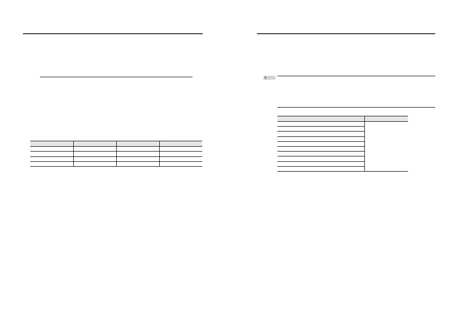
Sample calculation
Number of bytes
Data length
Communication speed
Response time
21
8 bit
9600 bps
26 ms
114
8 bit
9600 bps
143 ms
21
7 bit
38400 bps
6 ms
114
7 bit
38400 bps
33 ms
Communication Response Time
T6 (Sensor amplifier settings change time)
T6: 0ms
Data to which the setting changed after receiving response (after T5 elapses) is reflected can be
read using the data reading command (M0, MS) or DRQ input.
When writing to the following data number using the SW or AW command, the sensor amplifier is
reset.
The measured value after the setting is reflected can be read after T elapses.
When reading using the data reading command (M0, MS) or DRQ input before T elapses, the P.V.
value is read as "-99.998" (-------).
Data number
T
003: Reset request
Response time
005: Initial reset request
006: System parameter set request
010: Reference light registration request
011: Adjust request
012: Adjust reset request
100: Laser emission stop input
130: Measurement mode
131: Received/Blocked light mode
133: Averaging/High-pass filter
Point