KEYENCE DL-RS1A/IB User Manual
Page 14
12
Parameters of Commands and Responses
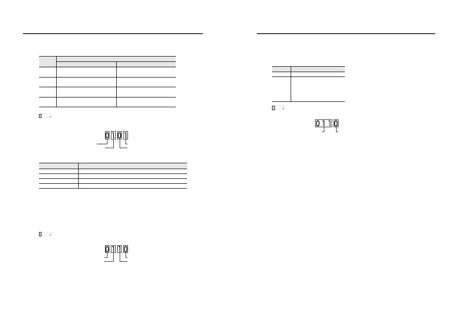
Convert the 2-digit number (ASCII characters) read to a binary number and check the ON/OFF
state of each bit to check the judgment output status and check output status.
• When the read data is "05":
"05" is converted to the binary number "0101".
When N.O.
*5
When the read data is one of the following values, it has a different meaning from that of an
evaluation value.
*6
When reading data from the amplifier unit whose "1. Measurement mode" is set to "Dimension
mode", the data format is changed to ±**.*** (Reading range -99.999 to +99.999).
*7
When the sensor amplifier is in the error status or "-----" state, the analog voltage output is
+5.500 and analog current output is +03.00.
*8
When writing is performed to set the prohibited combination of functions, the value becomes 1.
For details of each function, refer to the User's Manual.
*9
When the external input is ON, the external input status is "1" and when it is OFF, the state is "0".
The bit 0,1,2,3 corresponds to the external input 1,2,3,4.
• When the read data is "06":
"6" is converted to the binary number "0110".
*10 This item includes the results for the initial reset request.
Bit
Judgment output
When N.O.
When N.C.
0
0: HIGH judgment output OFF,
1: HIGH judgment output ON
0: HIGH judgment output ON,
1: HIGH judgment output OFF
1
0: LOW judgment output OFF,
1: LOW judgment output ON
0: LOW judgment output ON,
1: LOW judgment output OFF
2
0: GO judgment output OFF,
1: GO judgment output ON
0: GO judgment output ON,
1: GO judgment output OFF
3
0: Check output OFF,
1: Check output ON
0: Check output ON,
1: Check output OFF
Read data
Description
+EEE.EE
The sensor amplifiers is in the error status.
999.99
The value exceeds the upper limit of the display range.
-999.99
The value is -99.998 or below the lower limit of the display range.
-999.98
The value is "-----".
Reference
Bit 3: Check output OFF
Bit 0: HIGH judgment output ON
Bit 2: GO judgment output ON
Bit 1: LOW judgment output OFF
Reference
External input 4: OFF
External input 1: OFF
External input 3: ON
External input 2: ON
Parameters of Commands and Responses
*11 You can read data number "056" to check the system parameter of the sensor amplifier.
The system parameter means the polarity of judgment output and check output, and the setting
for analog output.
Convert the 2-digit number (ASCII characters) read to a binary number and check the ON/OFF
state of each bit to check the system parameter.
• When the read data is "006":
"6" converted to binary number is "0110".
Therefore, the setting of the amplifier from which the data is read is "NPN output" and
"Analog output 1 to 5 V".
*12 "Measured correction" and "Logical correction" results can be confirmed.
This cannot be used when "Do not correct" for "Calibration function" is selected.
Bit
Default settings
0
0: NPN output, 1: PNP output
3, 2, 1
000: Analog output OFF
001: 0 to 5 V
010: -5 to 5 V
011: 1 to 5 V
100: 4 to 20 mA
Reference
Bit 3, 2, 1: 1 to 5 V
Bit 0: NPN output