Communication response time, Communication response time and time chart – KEYENCE DL-RS1A/IB User Manual
Page 18
16
Parameters of Commands and Responses
Error numbers
The following table lists the error numbers that are returned as error responses when errors occur in
the communication with the IB Series.
Each error number is identified with two digits (ASCII characters).
The commands are only sent and received when a response is returned from DL-RS1A to the
external device within 1 sec.
Take the appropriate action to resolve the problem by referring to "Troubleshooting" (page 21).
Error
number
Error name
Problem
Action
00
Invalid command
error
An invalid command was
received.
Make sure that the external device has
sent a command listed in
"Communication commands" (page 10).
20
Data length error
Data with the correct length was
not received.
Make sure that the external device has sent
either "CR" or "CR + LF" as a data delimiter.
21
Number of
parameters error
The correct number of parameters
for the command was not
received.
Make sure that the number of parameters
and the positions of the commas used as
data delimiters conform to the command
format shown in "Commands and
Responses" (page 7).
22
Parameter error
·
A parameter exceeds its range
of value.
·
The external device is trying to
write a data type that cannot be
written.
·
The external device is trying to
read a data type that cannot be
read.
·
The data format is incorrect.
Make sure that the external device is
sending a command listed in
"Communication commands" (page 10).
29
Communication error
An error was detected with
RS-232C communication.
Make sure that DL-RS1A and the external
device have the same communication
settings configured. For information on
configuring DL-RS1A, refer to "(1)
Communication setup switches" (page 2).
65
ID number error
The ID number specified with the
command is incorrect.
Make sure that the sent data specified as
the ID number is a 2-digit number (ASCII
characters) according to the number of
connected units.
66
Expansion line error
The communication could not be
established due to a problem with
an expansion line.
Check that each of the sensor amplifiers
and DL-RS1A are securely and properly
connected by referring to "Connecting
the Unit to Sensor Amplifiers" (page 3).
Make sure that sensor amplifiers that are
supported by DL-RS1A are connected
(refer to page 4).
67
Write control error
DL-RS1A is not writable.
Change the read/write setting switch to
the R/W position to enable writing to DL-
RS1A. For information on the read/write
setting switch, refer to "Part Names and
Functions" (page 2).
Point
Communication Response Time
This section describes the communication response time for each communication command and
various time frames.
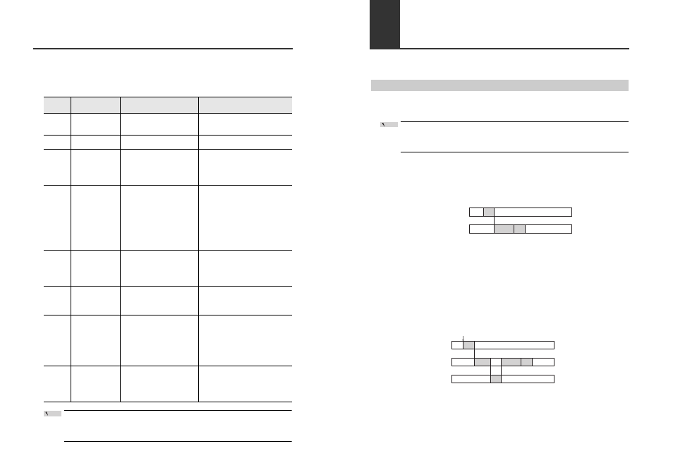
Communication Response Time and Time Chart
This section describes the concept of communication response time and the time chart for the
communication commands.
When sending communication commands consecutively from the external device, wait to send
the next command after reception of the response for the previous command from DL-RS1A
completes.
SR command
The SR command directly reads data from a sensor amplifier during T4 (DL-RS1A command
processing time).
Time chart
M0 command and MS command
The M0 and MS commands read the buffered data that DL-RS1A periodically retrieves from the
sensor amplifiers.
Therefore, the latest data detected by the sensors can only be read after T2 (DL-RS1A data
processing time) where DL-RS1A retrieves data from the sensor amplifiers.
Point
External device
DL-RS1A
T5
T3
T4
T3: Command format send time from external device
T4: DL-RS1A command processing time
T5: Response send time from DL-RS1A
* For the specific values (times) of T3 to T5, refer to
"Time Frames of Communication Response Time" (page 17).
Sensor amplifier
DL-RS1A
T1
T2
External device
T3
T5
T4
T1: Sensor amplifier response time (Refer to the instruction manual of the sensor amplifier.)
T2: DL-RS1A data processing time
T3: Command format send time from external device
T4: DL-RS1A command processing time
T5: Response send time from DL-RS1A
Detection
* For the specific values (times) of T2 to T5, refer to
"Time Frames of Communication Response Time" (page 17).