Assignment to out area (scanner to dl-ep1), Assignment to out area (scanner to dl-ep1) -15, 3 cyclic communication 3-15 – KEYENCE DL-EP1 User Manual
Page 45
3-3 Cyclic communication
3-15
3
C
om
m
uni
ca
tin
g
w
ith
the
G
T2
S
er
ies
- EtherNet/IP Compatible Network Unit DL-EP1 User’s Manual (GT2) -
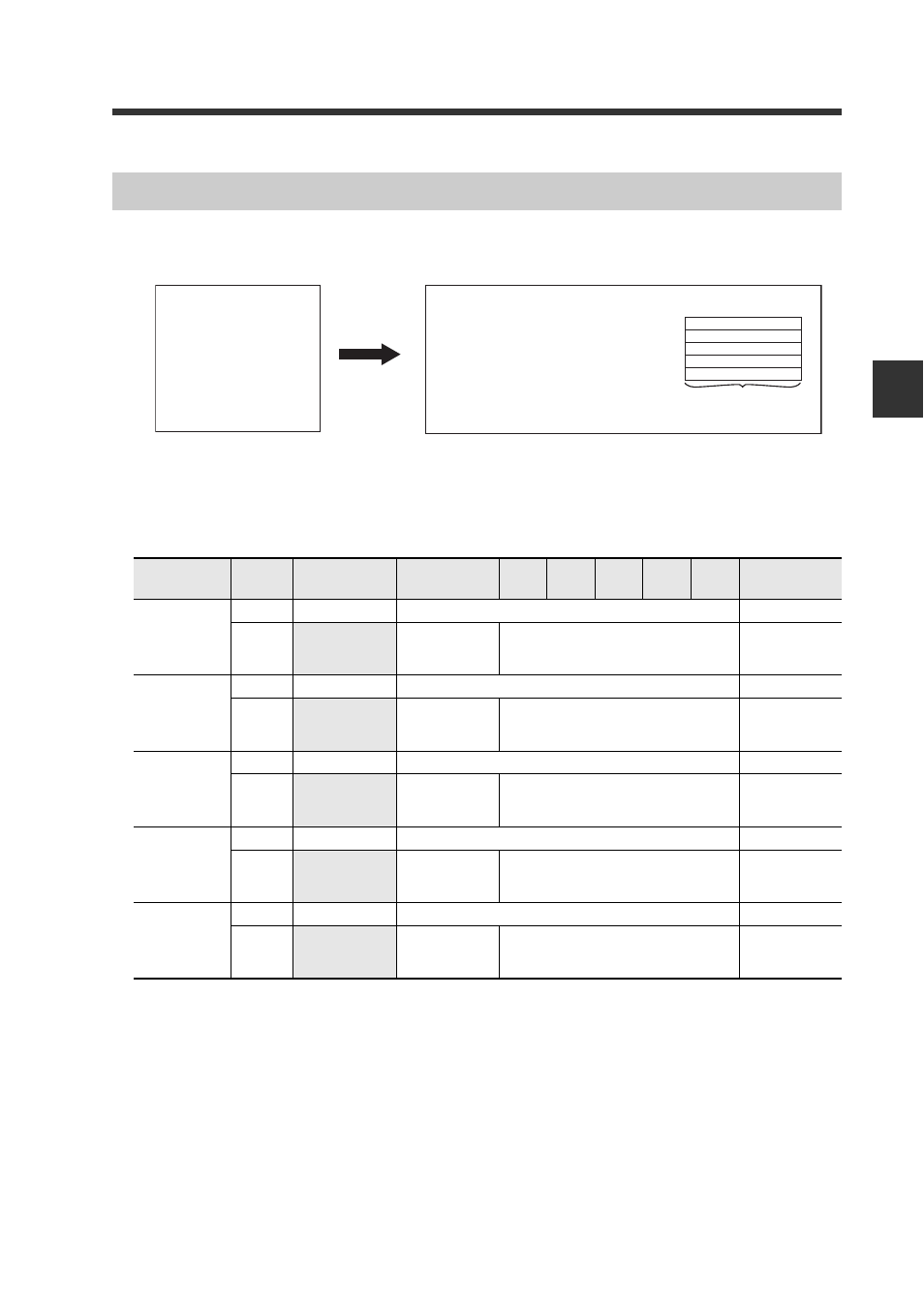
The data to the sensor amplifier is assigned to the OUT area of the EtherNet/IP
scanner.
External Input (5 Words (10 Bytes)) assembly instance (Instance ID): 65H
ID numbers (ID01 to ID15) are assigned for each sensor amplifier according to the
number of sensor amplifiers. The ID numbers representing unconnected sensor
amplifiers are not assigned.
Assignment to OUT Area (Scanner to DL-EP1)
DL-EP1 data
Scanner's OUT area
Address 0
Address 1
Address 9
External Input
(Assembly Instance: 101)
1-byte (8-bit) data
Name
Address
(Byte)
bit7
bit6
bit5
bit4
bit3
bit2
bit1
bit0
External
Input
Request 1
(Preset)
0
ID08
. . . . .
ID01
1
Reserved for
system
ID15
. . . . .
ID09
External
Input
Request 2
(Timing)
2
ID08
. . . . .
ID01
3
Reserved for
system
ID15
. . . . .
ID09
External
Input
Request 3
(Reset)
4
ID08
. . . . .
ID01
5
Reserved for
system
ID15
. . . . .
ID09
External
Input
Request 4
(Error Clear)
6
ID08
. . . . .
ID01
7
Reserved for
system
ID15
. . . . .
ID09
External
Input
Request 5
(Unassigned)
8
ID08
. . . . .
ID01
9
Reserved for
system
ID15
. . . . .
ID09