Section 4, Block reads, Scope – Hardy HI 2151/30WC Single-Scale Controller User Manual
Page 21: Transfer commands, Overview of transfer commands, Overview of block transfer commands
Section 4: Block Reads
15
SECTION 4 BLOCK READS
4.1.
SCOPE
Chapter 4 covers block read commands for the PROFIBUS Interface Option. Programmers
and users should be familiar with this chapter before operating the PROFIBUS Interface
Option.
4.2.
TRANSFER COMMANDS
4.2.1
OVERVIEW OF TRANSFER COMMANDS
1. PROFIBUS Interface Card maximum buffer size: 112 byte
2. Siemens PLC
TI 505 Series PLCs
Requires the Field Interface Module (FIM) to communicate over PROFIBUS.
Can continually exchange up to 32 words or 64 bytes for both PLC input and
output with each client device.
S5 Series PLCs
Requires IM 308C Module to communicate over PROFIBUS.
Can continually exchange up to 244 bytes for PLC input and output with each
client device.
S7 Series PLC
PROFIBUS ready, does not require additional modules.
Can continually exchange up to 244 bytes for PLC input and output with each
client device.
3. Allen-Bradley PLC5 Series
Requires PROFIBUS DP module to communicate over PROFIBUS.
Can continually exchange up to 244 bytes for both PLC Input and Output with
each client device.
4.2.2
OVERVIEW OF BLOCK TRANSFER COMMANDS
1. The PLC server determines the amount of bytes that can be
transferred; not the PROFIBUS interface option.
2. When using the HI 2151 Series PROFIBUS interface, the user can
select the Block Read Data Summaries and Block Write Commands as
required. However, the amount of bytes that can be transferred is
dependent on the data transfer capability of the server being used.
3. The ladder logic program provides the server with the ability to read
and write weight data by referencing the PROFIBUS address, the byte
numbers and number of bytes.
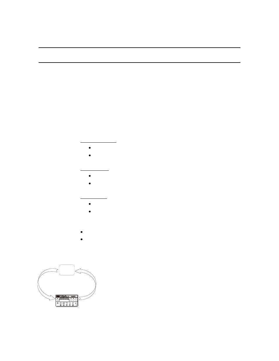
PLC
LADDER LOGIC
PROGRAM
WRITE/READ
#5400 (hex) +
BLOCK READ
DATA NUMBER
RESPONSE
# BETWEEN
14-20 or #23 (hex) +
DATA REQUESTED
DATA EXCHANGE
BLOCK TRANSFER