Hardy HI 2151/30WC Single-Scale Controller User Manual
Page 13
Section 2: Installation
7
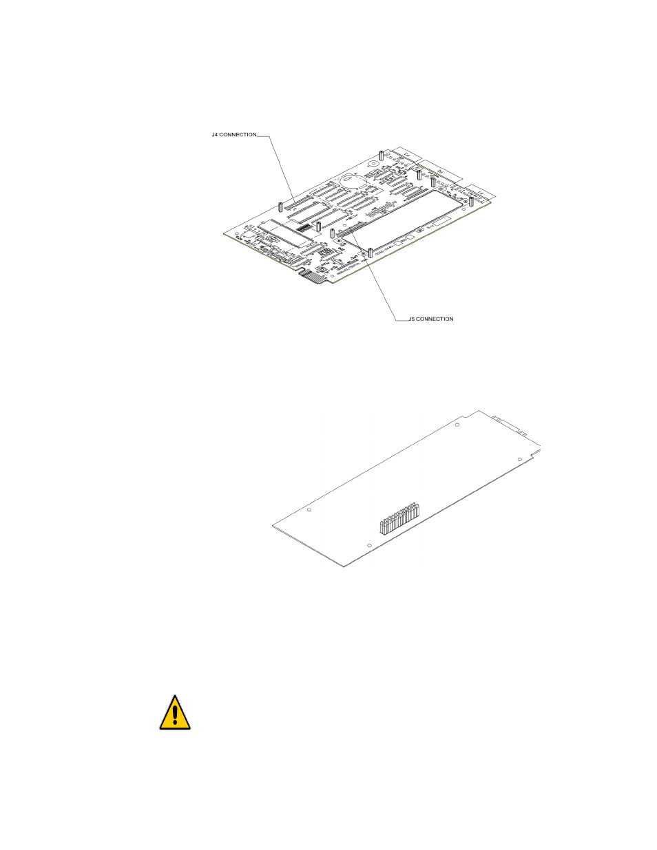
Figure 2-3
8. On the solder side of the PROFIBUS Interface Card, the side opposite the components,
there is a pin connector. (See Fig. 2-3)
Figure 2-4
9. With the pin connector side down, carefully plug the PROFIBUS Interface Card into
either connector J4 or J5 (See Fig. 2-2) whichever is available. These connectors also
refer to option 1 or option 2 on the rear panel. Option 1 uses connector J5. Option 2
uses connector J4. (See Fig. 2-4)
MAKE SURE THAT ALL THE PINS ARE PLUGGED INTO THE J4 OR
J5 CONNECTOR. FAILURE TO PROPERLY INSTALL THE PROFIBUS
INTERFACE CARD WILL RESULT IN PERSONAL INJURY OR
PROPERTY DAMAGE.