Retract installation – Hangar 9 P-51D Blue Nose 60 ARF User Manual
Page 9
16
Hangar 9 P-51 Mustang 60 ARF Assembly Manual
17
Hangar 9 P-51 Mustang 60 ARF Assembly Manual
Retract Installation
Required Parts
Wing panel (right and left)
Retract assembly (2)
Retract strut (right and left) #8 washer (8)
Retract servo (2)
Receiver
Transmitter
Receiver battery
2mm x 12mm retract screw (8)
2mm washer (8)
6-inch servo extension (2)
#2 x 3/8 screw (4)
3mm washer (4)
8-32 x 3/4-inch socket head screw (8)
3
1
/
2
-inch (90mm) wheel (2)
3mm x 8mm machine screw (4)
Tools and Adhesives
Side cutters
Threadlock
String or dental floss
T-pin
Medium CA
Pencil
Ruler
Drill
Pin drill
String or dental floss
Thin CA
Phillips screwdriver: #1, #2
Drill bit: 1/16-inch (1.5mm), 5/64-inch (2mm),
1/8-inch (3mm)
Hex wrench or ball driver: 1.5mm, 9/64-inch, 3mm
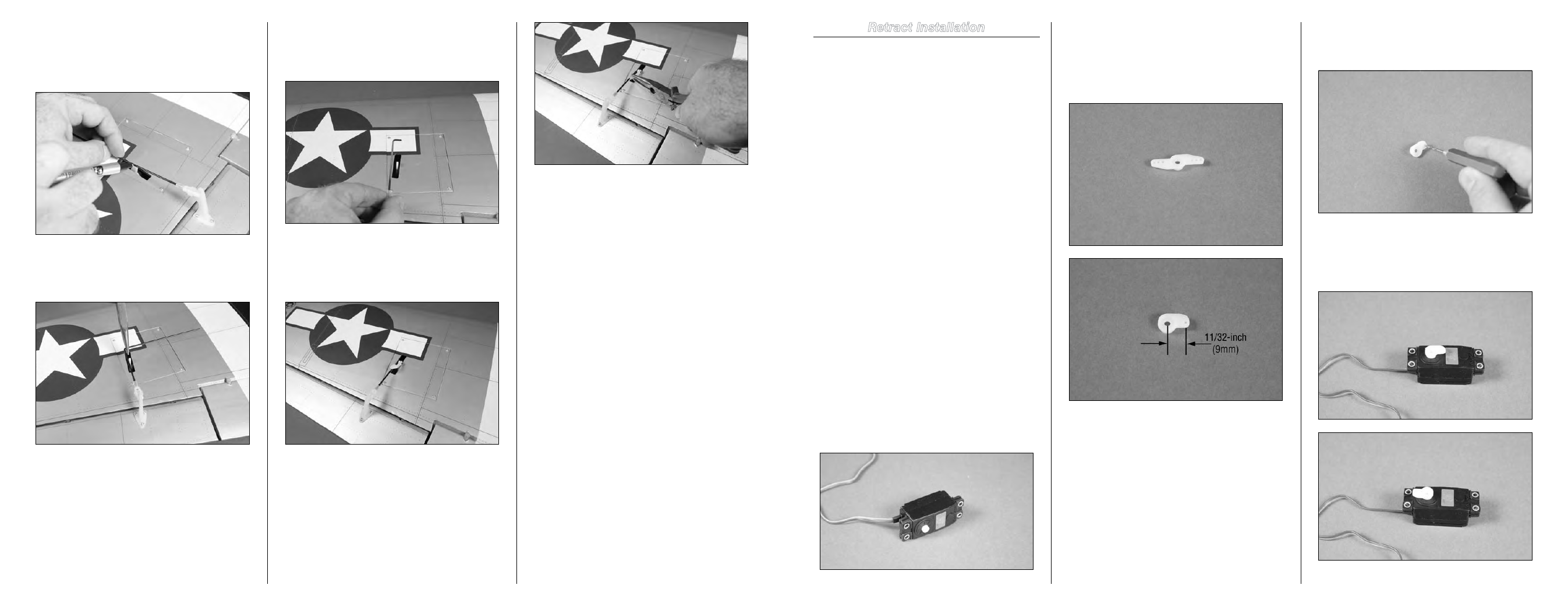
Step 1
Prepare the retract servo by installing the grommets and
brass eyelets. Note the eyelets are on the top-side of the
servo as shown. Remove the servo horn from the servo at
this time as well.
Step 2
Select a servo arm that has a hole located 11/32-inch (9mm)
from the center of the horn. Remove any arms that will not
be used using side cutters, leaving only the arm with the
hole as described. It is best to trim the arm down as small
as possible to fit into the retract mechanism without binding.
Step 3
Enlarge the hole in the servo horn using a 5/64-inch (2mm)
drill bit and pin drill.
Step 4
Place the servo horn on the retract servo so it moves equally
from the center position. You will need to use the radio
system to cycle the retract servo for this procedure.
Step 29
With the aileron aligned with the wing tip and aileron servo
centered, use a felt-tipped pen to mark the pushrod wire
where it crosses the hole in the servo arm that was enlarged
back in Step 14.
Step 30
Use pliers to bend the pushrod wire 90 degrees at the mark
made in the previous step.
Step 31
Use side cutters or a rotary tool and cutoff wheel to trim the
wire 3/8-inch (10mm) past the bend as shown. Use a flat file
to remove any sharp edges after cutting the wire.
Step 32
Insert the wire into the hole in the servo horn. Slide the
pushrod keeper on the wire, and then use pliers to snap it on
the wire to secure the pushrod wire to the servo arm.
Note
: You may need to adjust the clevis slightly to align
the aileron with the wing tip. Make sure the radio is on
and the aileron servo centered during this process.
Step 33
Repeat Steps 1 through 32 to install the remaining aileron
servo and linkage in the opposite wing panel.
Note
: The retracts are installed next and prior to
installing the flap servos so that you have access
through the flap servo hatch to route the retract
extensions.