Hinging the control surfaces – Hangar 9 P-51D Blue Nose 60 ARF User Manual
Page 4
6
Hangar 9 P-51 Mustang 60 ARF Assembly Manual
7
Hangar 9 P-51 Mustang 60 ARF Assembly Manual
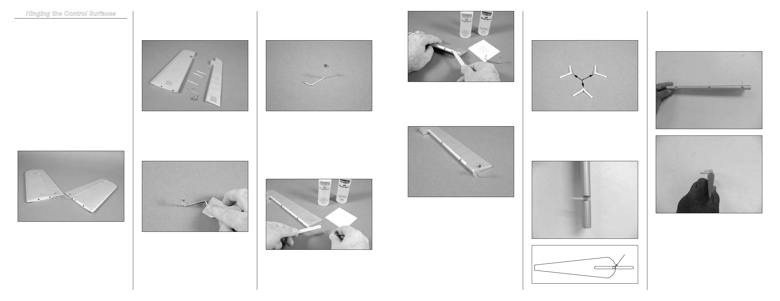
Step 6
Insert the wire into the hole in the elevator. Wrap a piece of
low-tack tape around the elevator to keep the wire secure
until the epoxy fully cures. While the epoxy cures we can
continue the hinging process then hinge the elevator last.
Step 7
Locate three hinges. Apply a small amount of petroleum jelly
to each hinge where it bends to prevent it from accidentally
being glued and preventing it from operating correctly.
Step 8
Insert the hinges into the control surface. Moving the hinge
over 90 degrees and pressing the hinge into the surface will
set the correct depth for the hinge, as the hinge point will
be recessed slightly in the control surface so it operates
properly.
Hinge point recessed in control surface
Step 9
In addition to setting the correct depth of the hinge, this will
guarantee that the hinge has been installed in the correct
direction. Rotating the hinge could cause the surface to bind,
increasing the load on the servo and draining the receiver
battery prematurely.
Hinging the Control Surfaces
Required Parts
Fuselage
Rudder
Hinge (3)
Wing panel with aileron and flap (right and left)
Stabilizer and elevator (right and left)
Elevator torque rod (right and left)
Tools and Adhesives
Hinge glue
30-minute epoxy
Sandpaper
Mixing stick
Low-tack tape
Paper towel
Rubbing alcohol
Petroleum jelly
Step 1
Locate the stabilizer and elevator assemblies. Note the
direction and location of the elevator control horn in
relationship to the stabilizer. It is suggested to use a small
piece of low-tack tape to mark one of the assemblies so the
elevator and stabilizer can be returned to their pairing.
Step 2
Separate the elevator and stabilizer. Remove the elevator
control horn and three hinges. Set the stabilizer and hinges
aside in a safe place.
Step 3
Use a piece of sandpaper to roughen the wire from the
elevator control horn where it contacts the elevator. This
provides a better surface for the epoxy to adhere to when
glued in position. Use a paper towel and rubbing alcohol to
remove any oils or debris from the wire after sanding.
Step 4
Thread the nylon horn on the wire so it is flush with the end
of the wire and facing the opposite direction of the portion of
the wire that will go into the elevator.
Note
: You can perform the following steps for both
elevator halves with one batch of epoxy. Read through
the steps to familiarize yourself with the procedure
before mixing any epoxy.
Step 5
Mix a small amount of 30-minute epoxy. Apply the epoxy to
the notch and into the hole in the elevator, as well as to the
portion of the wire that will contact the elevator.
Note
: Make sure to use enough epoxy to glue the
torque rods. If the epoxy does not ooze out between
the torque rod and elevator, you have not used enough
epoxy.