Receiver, rudder servo and tail wheel installation – Hangar 9 P-51D Blue Nose 60 ARF User Manual
Page 14
26
Hangar 9 P-51 Mustang 60 ARF Assembly Manual
27
Hangar 9 P-51 Mustang 60 ARF Assembly Manual
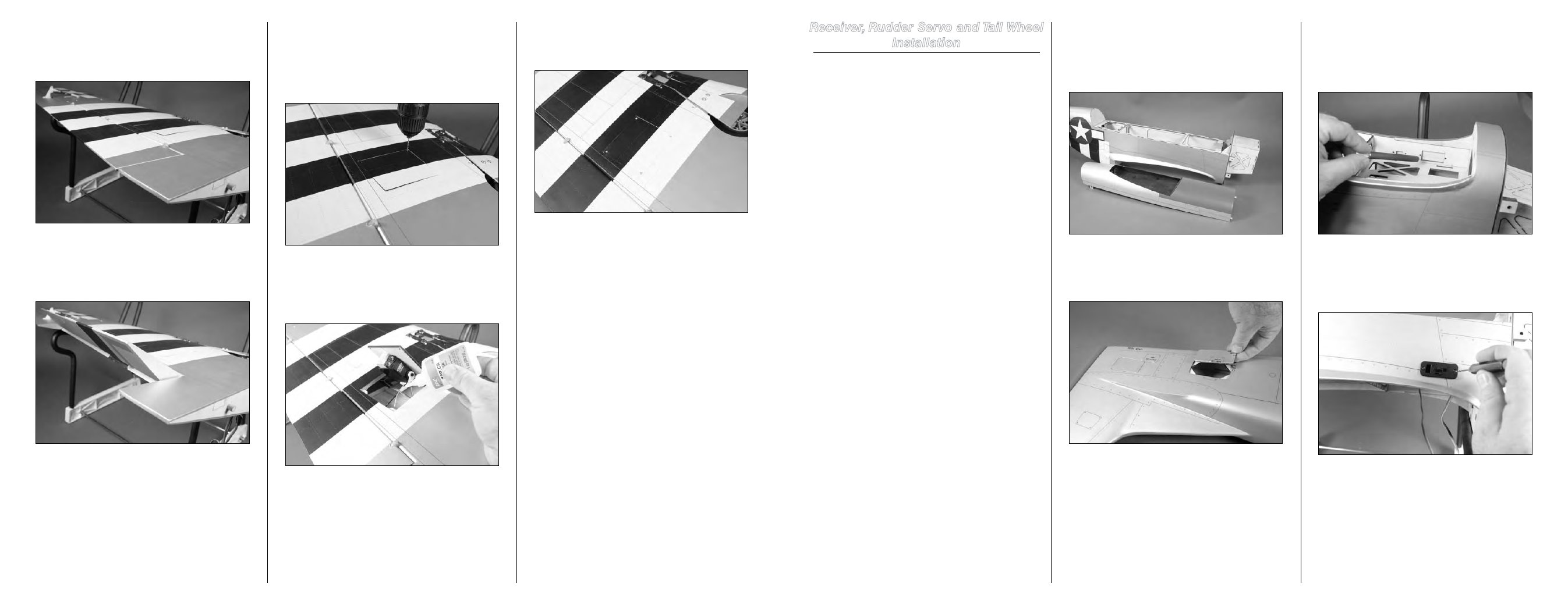
Receiver, Rudder Servo and Tail Wheel
Installation
Required Parts
Fuselage
Tail gear wire with wheel
Tail gear steering arm
Pushrod connector
1.5mm washer
C-clip
2.5mm wheel collar (2)
3mm setscrew (3)
Clevis
Clevis safety tubing
Servo
Receiver
Transmitter
Receiver battery
Pushrod keeper
Switch harness
Control horn with backplate
2mm x 32mm machine screw (3)
#2 x 3/8-inch sheet metal screw (4)
Pushrod wire, 30
1
/
2
-inch (775mm)
Tools and Adhesives
Hook and loop strap
Pin drill
Felt-tipped pen
1/4-inch (6mm) foam
Pliers
Side cutter
Rubbing alcohol
Paper towel
Pencil
Thin CA
Phillips screwdriver: #1
Threadlock
Rotary tool with cutoff wheel T-pin
Hobby knife with #11 blade
Hex wrench: 1.5mm (included)
6-inch (152mm) servo extension (4)
Drill bit: 1/16-inch (1.5mm), 5/64-inch (2mm)
Extensions for 7-Channel Receiver Installation
3-inch (76mm) servo extension (2)
Y-harness (2)
Extensions for 9-Channel Receiver Installation
3-inch (76mm) servo extension (6)
Step 1
Remove the fuselage hatch from the fuselage by lifting it
up at the rear to release the magnets. Slide the hatch to the
rear of the fuselage to release the pegs at the front and set it
aside.
Step 2
Remove the access cover for the tail wheel from the
fuselage. Set it aside with the fuselage hatch.
Note
: Steps 3 through 6 are for mounting the switch
harness and receiver battery for glow-powered models.
If you are preparing your model for electric power, you
can skip to Step 7 and mount the receiver.
Step 3
Use a hobby knife to remove the balsa from the side of the
fuselage for mounting your particular switch. The plywood
will have the correct cutout for the most common switches
available.
Step 4
Place your switch harness into the appropriate hole. Use a
pin drill and 1/16-inch (1.5mm) drill bit to drill the two holes
necessary to mount the switch to the fuselage.
Step 22
After setting the throws to 0%, move the switch on the radio
to the “up” position. Adjust the throw at the radio until the
flap is aligned with the trailing edge of the wing.
Step 23
Move the switch on the radio to the “down” position. Adjust
the throw at the radio until the flap is set at the measurement
listed under “Control Throws” for down flap.
Step 24
Use a T-pin to poke through the four holes in the covering in
the flap servo cover. Position the servo cover in the wing and
use a 1/16-inch (1.5mm) drill bit to drill the four holes for
the servo cover mounting holes. Use caution or you could
accidentally drill through the top of the wing.
Step 25
Apply 2–3 drops of thin CA into each hole to harden the
surrounding wood. This provides a harder surface for the
screws making them more secure when installed.
Step 26
Use a #1 Phillips screwdriver and four #2 x 3/8-inch sheet
metal screws to secure the servo cover to the wing.
Step 27
Repeat Steps 1 through 26 for the remaining flap servo
installation.