Hangar 9 P-51D Blue Nose 60 ARF User Manual
Page 20
38
Hangar 9 P-51 Mustang 60 ARF Assembly Manual
39
Hangar 9 P-51 Mustang 60 ARF Assembly Manual
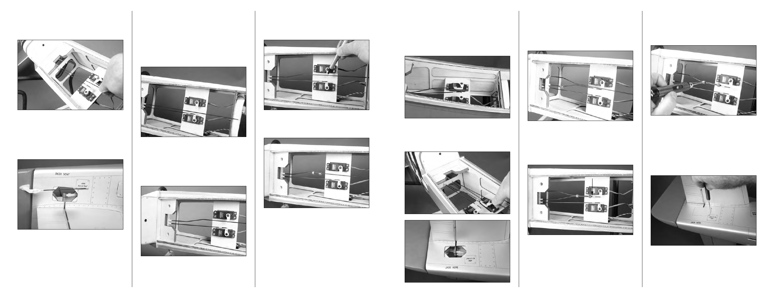
Step 22
Use pliers to bend the pushrod wire 90 degrees at the mark
made in the previous step. Trim the wire 3/8-inch (10mm)
above the bend using side cutters or a rotary tool. Insert the
wire into the hole in the servo arm. Slide the pushrod keeper
onto the wire, then rotate it and snap it on the wire to secure
the pushrod wire to the servo horn.
Step 23
Repeat Steps 16 and 17 to install the remaining 30
1
/
2
-inch
(775mm) pushrod wire.
Step 24
You will need to make two slight bends in the elevator
pushrod to align it with the first elevator pushrod wire
as shown. Make sure the bend is at least 1-inch (25mm)
forward of the pushrod tube so the bend does not bind in the
tube when operating the elevator.
Step 25
Use a rotary tool and cut off wheel or side cutters to trim the
pushrod wire so it almost touches the pushrod keeper. Slide
the wheel collars forward. Slide the bent pushrod wire into
the wheel collars.
Step 26
Use two 3mm x 3mm setscrews and a 1.5mm hex wrench to
secure the collars that link the two pushrods together. Make
absolute sure to use threadlock on these screws so they
don’t vibrate loose.
Step 27
Place the access cover back in place on the fuselage. Check
to make sure the trim scheme matches and that you are
not installing the cover on the wrong side of the aircraft.
Use a pin drill and 1/16-inch (1.5mm) drill bit to drill four
holes through the cover and into the fuselage. Make sure to
position the holes so they are roughly 3/32-inch (2mm) from
the edges of the cover.
Step 16
Slide one of the 30
1
/
2
-inch (775mm) pushrods, threaded end
first, into the elevator pushrod tube closest to the center line
of the fuselage inside of the fuselage.
Step 17
Cut a 1/4-inch (6mm) piece from the clevis safety tubing
and slide it over the clevis. Thread the clevis 10 turns on the
pushrod wire. Connect the clevis to the elevator control horn.
Slide the tubing over the clevis so it will not accidentally
open in flight.
Step 18
Use the radio system to center the servo for the elevator.
Remove the original arm from the elevator servo and install
a 180-degree arm so it is perpendicular to the center line of
the servo. You will be connecting the linkage to a hole that
is 9/16-inch (14mm) from the center of the servo horn, so
make sure your servo horn meets these requirements. Use
side cutters to remove any unused arms from the servo horn
that may interfere with the operation of the servo.
Step 19
You will need to make two slight bends in one elevator
pushrod to align it with the elevator servo horn as shown.
Make sure the bend is at least 1-inch (25mm) forward of the
pushrod tube so the bend does not bind in the tube when
operating the elevator.
Step 20
With the radio system on and the elevator centered, use a
felt-tipped pen to mark the pushrod wire where it crosses the
hole of the servo horn previously enlarged.
Step 21
Slide two 4mm wheel collars on the pushrod wire.