Engine installation: 4-stroke – Hangar 9 P-51D Blue Nose 60 ARF User Manual
Page 21
40
Hangar 9 P-51 Mustang 60 ARF Assembly Manual
41
Hangar 9 P-51 Mustang 60 ARF Assembly Manual
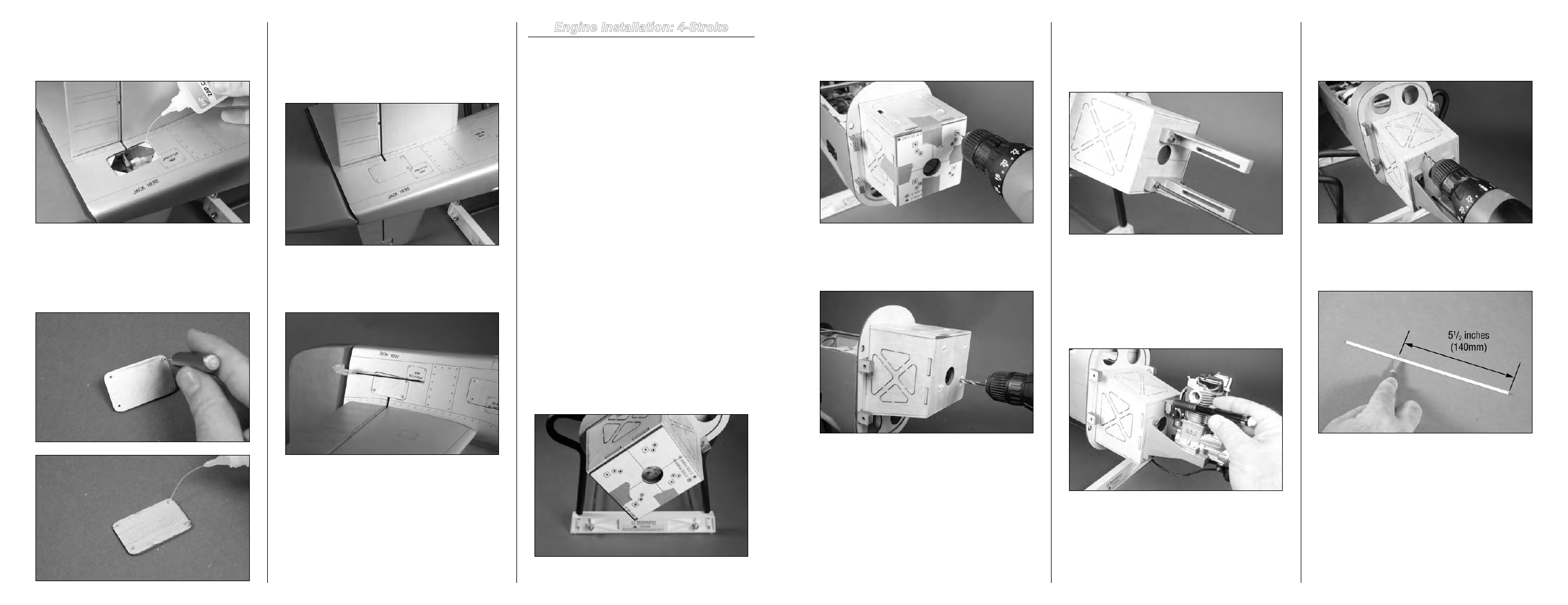
Step 2
Using a drill and 1/16-inch (1.5mm) drill bit, drill through the
template and through the firewall for the mount that fits your
particular engine.
Step 3
Remove the template from the firewall. Use a drill and 7/32-
inch (5.5mm) drill bit to enlarge the holes in the firewall.
Step 4
Use four 8-32 x 3/4-inch socket head bolts, four #8 washers
and four 8-32 blind nuts to secure the mount rails to the
firewall. Tighten the screws using a 9/64-inch hex wrench or
ball driver.
Important
: Make sure to use threadlock on all metal-
to-metal fasteners.
Step 5
Slide the engine into position between the engine mount
rails. Use a pencil to mark the location for the throttle
pushrod wire on the firewall.
Note
: If you are using a regular four-stroke, make
sure the carburetor arm is facing the same direction as
shown in the photo above.
Step 6
Remove the engine from the rails. Use a drill and 5/32-inch
(4mm) drill bit to drill a hole through the firewall for the
throttle pushrod tube.
Step 7
Use a hobby knife with a #11 blade to cut the throttle
pushrod to a length of 5
1
/
2
inches (140mm).
Step 28
Apply 2–3 drops of thin CA into each hole to harden the
surrounding wood. This provides a harder surface for the
screws making them more secure when installed.
Step 29
Use a 5/64-inch (2mm) drill bit to enlarge the holes in the
cover. Apply 2–3 drops of thin CA into each hole to harden
the surrounding wood. This will harden the wood and help it
hold up to the pressure of the screws over time.
Step 30
Secure the cover to the fuselage using four #2 x 3/8-inch
sheet metal screws. Use a #1 Phillips screwdriver to tighten
the four screws. The screws only need to be tight enough to
secure the cover; don’t tighten them too much and crush the
wood of the cover.
Step 31
Repeat Steps 27 through 30 to install the remaining elevator
access cover.
Engine Installation: 4-Stroke
Required Parts
Fuselage assembly
Firewall template
8-32 blind nut (4)
Engine mount rail (2)
#8 washer (8)
Clevis
Safety tubing
Plywood pushrod support
Throttle servo with hardware 8-32 lock nut (4)
8-32 x 3/4-inch socket head bolt (4)
8-32 x 1
1
/
4
-inch socket head bolt (4)
Pushrod tube, 8
1
/
8
-inch (206mm)
Pushrod wire, 13
1
/
4
-inch (335mm)
Tools and Adhesives
Low-tack tape
Drill
Side cutters
Felt-tipped pen
Hobby knife with #11 blade Medium grit sandpaper
Phillips screwdriver: #1, #2 Medium CA
Pencil
Thin CA
Pliers or Z-bend pliers
Hex wrench or ball driver: 9/64-inch
Nut driver or socket: 11/32-inch
Drill bit: 1/16-inch (1.5mm), 5/32-inch (4mm),
7/32-inch (5.5mm)
Step 1
Locate the firewall template. Use low-tack tape to secure it
to the engine box. A paper copy of the engine template is
located on Page 71 of this manual.