Hangar 9 P-51D Blue Nose 60 ARF User Manual
Page 17
32
Hangar 9 P-51 Mustang 60 ARF Assembly Manual
33
Hangar 9 P-51 Mustang 60 ARF Assembly Manual
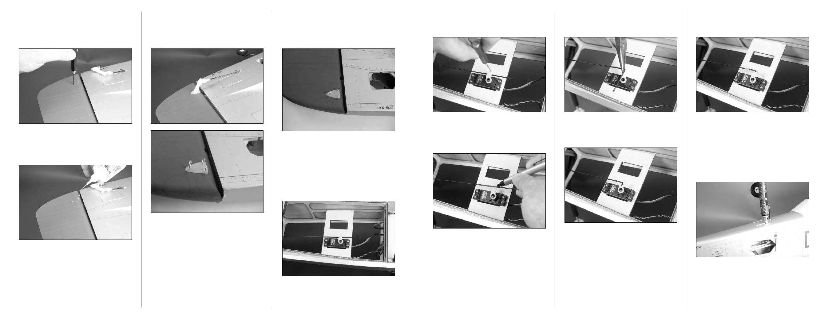
Step 30
Use a 5/64-inch (2mm) drill and pin drill to enlarge the hole
that is 9/16-inch (15mm) from the center of the servo arm.
Step 31
Make sure the rudder and rudder servo are centered. Use a
felt-tipped pen to mark the pushrod where it crosses the hole
in the servo arm enlarged in the previous step.
Step 32
Use pliers to bend the pushrod wire 90-degrees at the mark
made in the previous step.
Step 33
Use side cutters to trim the pushrod wire so only 3/8-inch
(10mm) of the wire remains beyond the bend.
Step 34
Use a pushrod keeper to secure the pushrod wire to the
servo horn.
Step 35
It is now time to secure the connector at the tail gear wire
to the pushrod. You will need to deflect the rudder slightly
so the setscrew can be accessed. Use a 1.5mm hex wrench
to tighten the setscrew that secures the connector to the
pushrod wire. Make sure that when the rudder is centered,
the tail wheel is centered as well. It may take a try or two to
get it correct. You will want to make sure to use threadlock
on this setscrew as accessing in the future will be difficult.
Hint: Use a file to make a flat spot on the pushrod wire
for the setscrew. This will make the connection between
the wire and setscrew more secure and less likely to
slip.
Step 25
Use a pin drill and 5/64-inch (2mm) drill bit to drill the three
holes through the rudder to mount the control horn. Use
care to drill the holes parallel in the rudder so the backplate
can be installed on the opposite side of the rudder.
Step 26
Apply 2–3 drops of thin CA into each hole to harden the
surrounding wood. This provides a harder surface for the
screws making them more secure when installed.
Step 27
Once the CA has cured, you can attach the control horn to
the rudder using three 2mm x 32mm machine screws and
the control horn backplate. Use a #1 Phillips screwdriver to
tighten the screws.
Step 28
Use side cutters to trim the length of the screws down. Use
a flat file to remove any sharp edges from the screws so they
don’t accidentally damage anything during the transport of
your aircraft.
Step 29
Use the radio system to center the servo for the rudder.
Remove the original arm from the rudder servo and install
a 180-degree arm so it is perpendicular to the center line of
the servo. You will be connecting the linkage to a hole that
is 9/16-inch (14mm) from the center of the servo horn, so
make sure your servo horn meets these requirements. Use
side cutters to remove any unused arms from the servo horn
that may interfere with the operation of the servo.