Hangar 9 P-51D Blue Nose 60 ARF User Manual
Page 27
52
Hangar 9 P-51 Mustang 60 ARF Assembly Manual
53
Hangar 9 P-51 Mustang 60 ARF Assembly Manual
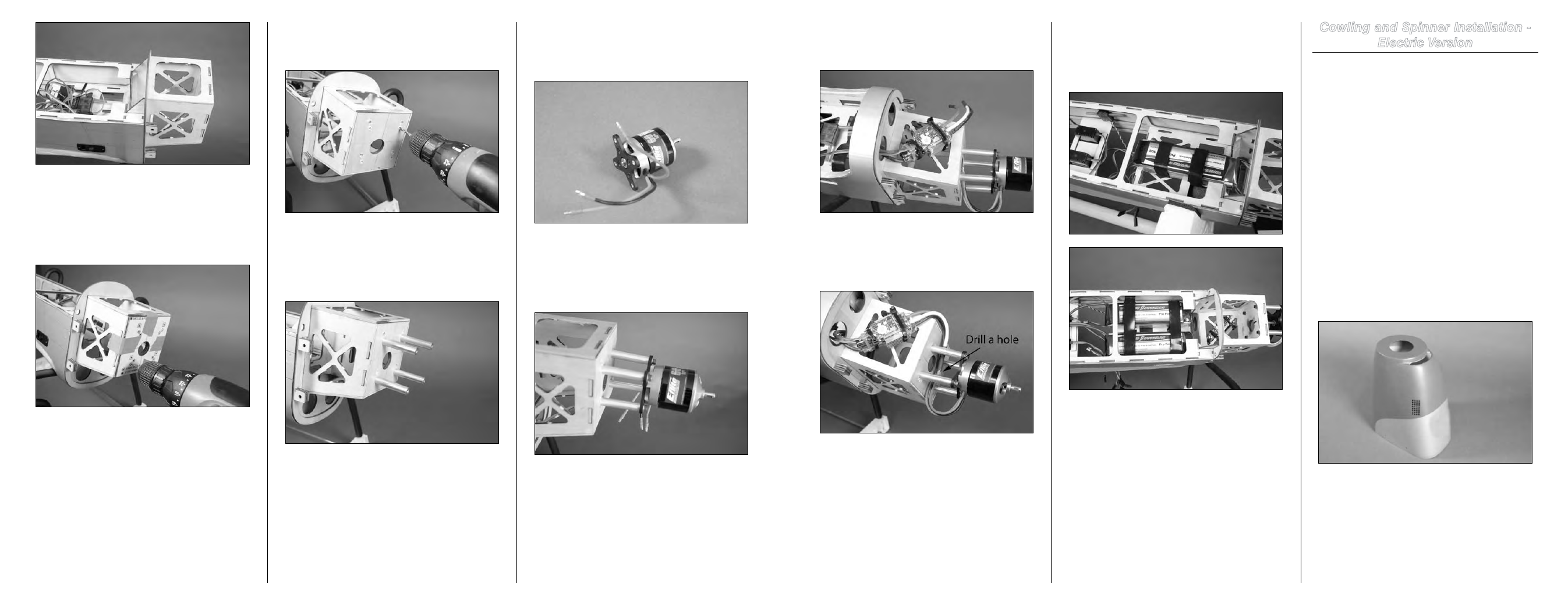
Step 7
Secure the electronic speed control to the bottom of the
motor box using two-sided tape and tie wraps.
Step 8
Connect the leads between the speed control and motor. Use
tie wraps to secure the wiring so it will not get entangled in
the moving parts of the motor.
Hint
: Drill a 5/32-inch (4mm) hole through the firewall
so a tie wrap can be used to secure the wiring to the
firewall as shown.
Step 9
Plug the lead from the speed control into the throttle channel
of the receiver at this time.
Step 10
The batteries are mounted in the fuselage from the top side.
Use hook and loop straps to secure them in the fuselage.
It may be necessary to use hook and loop tape to keep the
batteries from sliding on the battery tray in the fuselage.
Note
: The second photo shows the dual battery
configuration for the Power 90.
Step 11
At this time check the operation of the motor using the radio
system. It should rotate counterclockwise when viewed
from the front of the fuselage. If it does not, refer to the
instructions included with the speed control to correct the
direction of rotation.
Cowling and Spinner Installation -
Electric Version
Required Parts
Fuselage assembly
Cowling
Spinner assembly
Propeller adapter
Propeller
Propeller nut
Spinner backplate spacer
3mm x 15mm socket head machine screw (4)
Tools and Adhesives
Rotary tool with sanding drum
Hobby knife with #11 blade
Hobby scissors
Box or open end wrench: 12mm
Hex wrench or ball driver: 2.5mm, 5/32-inch
Step 1
Carefully cut the opening in the front of the cowling to allow
cooling air to pass through the cowling. Use a rotary tool
with a sanding drum to clean up any rough edges left from
the hobby scissors.
Note
: Both motor options (Power 60 and Power 90)
have been tested and only require the opening in the
front of the cowling to allow cooling air to pass into the
fuselage.
Step 2
Locate the firewall template. Use low-tack tape to secure it
to the engine box. Use a drill and 1/16-inch (1.5mm) drill
bit, drill through the template and through the firewall for the
mount that fits your particular motor. A paper copy of the
engine template is located on Page 71 of this manual.
Step 3
Remove the template from the firewall. Use a drill and 5/32-
inch (4mm) drill bit to enlarge the holes in the firewall.
Step 4
Use four 8-32 x 3/4-inch socket head bolts and four #8
washers to secure the aluminum motor standoffs to the
firewall. Use a 9/64-inch hex wrench or ball driver to tighten
the bolts.
Important
: Make sure to use threadlock on all metal-
to-metal fasteners to prevent them from vibrating loose.
Step 5
Use a 2.5mm hex wrench or ball driver to attach the
X-mount to the motor using the screws provided with the
motor. Make sure to use threadlock on these screws as well.
Step 6
Use four 8-32 x 3/4-inch socket head bolts and four #8
washers to secure the motor to the aluminum standoffs. Use
threadlock on the screws before tightening them with a 9/64-
inch hex wrench or ball driver.