Pulley-wheel installation – Cannon Instrument CMRV-5000 User Manual
Page 19
13
CANNON
®
Mini-Rotary Viscometer
CMRV-5000 Instruction & Operation Manual
Version 1.0b—August, 2011; CANNON
®
Instrument Company
2139 High Tech Road • State College, PA • 16803 • USA
Serial connections
To connect a single CMRV-5000 instrument to the host computer,
connect the computer cable to the RS-232, DB-9-pin socket at the rear of
the CMRV-5000 Controller and secure the cable connection with the two
small screws on the ears of the plug. Attach the other end of the cable to
the RS-232 port at the rear of your computer.
NOTES
COM 2 and COM 4 use the same IRQ settings on most computers,
meaning that they cannot be used simultaneously. The COM 1 and COM
3 ports have the same problem. Do not try to use a device on COM 4 if
you are using COM 2 for the CMRV instrument.
Some display adaptors (in particular, S3, 8514A and ATI mach 8) have an
address conflict with COM 4 ports. If this is the case, you may need to
use another COM port or replace your current display adaptor.
RS-485 serial connections
To install multiple CMRV units using RS-485 serial cable connections,
see the multi-unit configuration instructions in APPENDIX D.
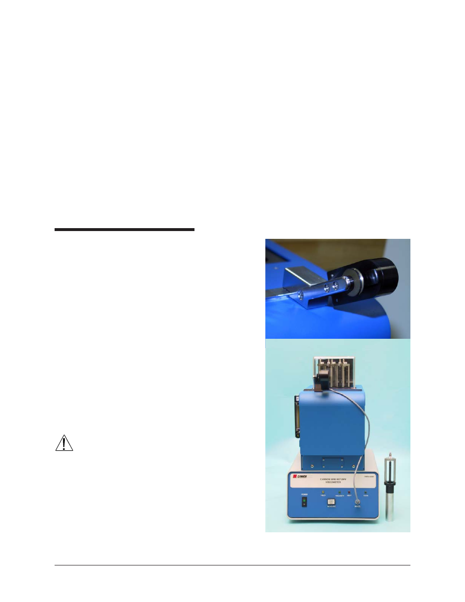
Pulley-wheel installation
To install the pulley-wheel
assembly atop the CMRV-
5000, slide it onto the
stainless steel slide track
atop the head unit with the
pulley-wheel facing out
(see photo). The bevelled
fitting on the base of the
pulley-wheel assembly will
mate with the slide-track to
secure the assembly to the
head unit. The pulley-
wheel should be positioned
on the track opposite the
viscometer during testing.
The scored lines on the
track will assist with
orientation.
CAUTION
Use care in handling the
pulley-wheel assembly to
avoid damage to the wheel
or the movement sensor.
Make sure that the assem-
bly is seated securely on
the track prior to testing.
With the power off, plug
the free end of the pulley-
wheel sensor wire into the
jack labelled WHEEL on the front of the CMRV-5000 Controller.