Major operating controls and their functions, I top view 1, Power on/off button (power) – Panasonic WJ-MX50 User Manual
Page 5: Positioner joystick, Positioner on/off button (on), Scene grabber on/off button (scene grabber), G. color - b button (b)
Attention! The text in this document has been recognized automatically. To view the original document, you can use the "Original mode".
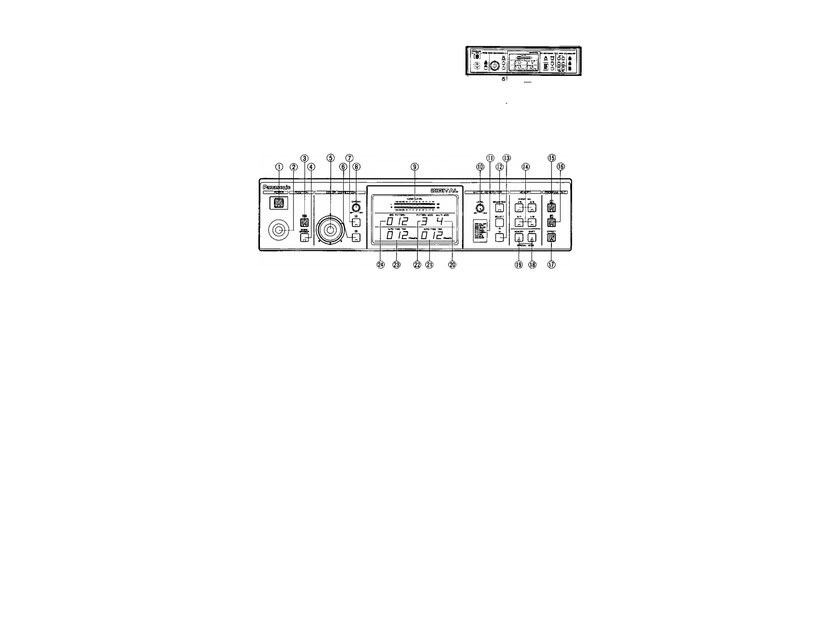
MAJOR OPERATING CONTROLS AND THEIR FUNCTIONS
I TOP VIEW 1
ns nn
^ ^ £ S
A a .6. A
fiS Q ¿fiiflOflCl
iSi 0 ChQ
I
iii A
Q_Q_0
________ *Cha
■liirr ■ - i
2
.
3.
4.
Power ON/OFF Button (POWER)
Press this button to turn on the power of the unit.
The LED on this button lights and the following LEDs
light up at the same time. C/L BAR on the Matte
Color Indicator (11), Effect-Out Button (17), One-Way
Button (27), Straight Wipe Button (70), Effect ON/OFF
Button (59), Effect-A Button (58), Repeat Effect Button
(54), DSK'A Button (45), Matte Button (47), Wipe Select
Button (74), Source Ion A-bus Button (102), SouCG 2 on
B-Bus Button (101), Audio Follow ON/OFF Button (79)
and Black Fade Button (85). These LED’s light up only
when the Reset ON/OFF Switch (109) is turned on.
Notes:
1. The Main Power Switch (in back) (131) must be on
before the Power ON/OFF Button (1) is pressed
2. When the Editing Controller AG-A800 is used with
WJ-MX50, the power of AG-A800 should be off
first to turn off the power of WJ-MX50. The power
of WJ-MX50 can not be turned off by-itself.
3. Read Note 3 on page 17,
Positioner Joystick
The position of the wipe pattern as selected using the
Square Wipe Button (60) can be freely set using this
Joystick control.
Positioner ON/OFF Button (ON)
This button must be pressed to operate the Positioner
Joystick (2),
Scene Grabber ON/OFF Button
(SCENE GRABBER)
The scene wiped by the Square Wipe Button (60) will
be grabbed by pressing this button. The position of this
area can then be changed by operating the Positioner
Joystick (2).
5. RGB Control
This Joystick Control permits you to balance or change
the hue from the images of the Source Video Signal
(either A or B) by moving its position. When' this
Controller is positioned at center, it generates the
original color of the Source Video Signal.
G. Color - B Button (B)
Color correction can be made on the B - bus Source
Video Signal by pressing this button. When you press it
once, the LED starts blinking, the chroma level can be
changed by using the Chroma Level Control (8).
When you press a second time, the LED is continuously
turned on, the hue can be changed by using the RGB
Control (5) in addition to the chroma level by using the
Chroma Level Control (8).
7. Color - A Button (A)
Color correction can be made on the'A - bus Source
Video Signal by pressing this button. When you press it
once, the LED starts blinking, the chroma level can be
changed by using the Chroma Level Control (8).
When you press a second time, the LED is continuously
turned on, the hue can be changed by using the RGB
Control (5) in addition to the chroma level by using the
Chroma Level Control (8).
8. Chroma Level Control (CHROMA)
This Control adjusts the color level of the images from
the Source Video Signal. When this Control is set to
the center position, it generates the original color level
of the Source Video Signal.
Note :
The noise may be recorded on tape when this
control is adjusted to the MAX with excessive
color input signal.
- A -