Operation, A-1. power, A-2. resetswitch – Panasonic WJ-MX50 User Manual
Page 16: A-3. demo switch 1. on position
Attention! The text in this document has been recognized automatically. To view the original document, you can use the "Original mode".
The following models {or equivalents} are recommended in
this system. The S-Video signal and balanced audio signal
are also recommended to use obtaining a quality edited
outputs.
Digital AV Mixer:
WJ-MX50
Character Generator:
WJ-KB50
External Camera ;
WV-D5100
Playback VTR:
AG-7650
Recording VTR :
AG-7750
Editing Controller;
AG-A800
Monitor TV
(I)
Connect the coaxial cables between the Advance
Reference
Output
Connectors (130) on the WJ-MX50
and the REF-IN connector on both Playback VTR-1 and
-
2
.
{2} Connect the audio cables between the Source 1 Audio
Input Conector (141) /Source 2 Audio Input Connector
(140)/Program Out-1 Audio Output Connector (135) on
the WJ-MX50 and the.AUDIO OUT connector/AUDIO
IN
connector
on
the
PlaybackVTR-1/Playback
VTR-2/Recording VTR respectively.
(3) Set the Source Selection Switch (114)onthe WJ-MX50
to the Si -2 position.
(4)
Connect
the
control
cables
between
the
PLAYER-1/PLAYER-2/RECORDER connectors on the
Interface Unit of AG-A800 and the REMOTE connector
on the Playback VTR-1/Playback VTR-2/Recording
VTR respectively.
(5) Connect the S-Video Cables between the Source 1
Y/C Input Connector (111)/Source 2 Y/C Connector
(113)/Program Out-1 Y/C Output Connector (124)
on the WJ-MX50 and the S-VIDEO OUT/S-VIDEO
IN connectors on the Playback VTR-1 /Playback
VTR-2/Recording VTR respectively.
(6) Connect the coaxial cable between the Black Burst
Output Connector (128) on the WJ-MX50 and the REF
IN connector on the Interface Unit of AG-A800.
(7) Connect the control cable between the Editing Control
Connector (132) and the SW l/F connector on the
interface Unit of AG-A-800.
(8) Connect the control cable between the TO l/F UNIT
connector on the AG-A800 and the TO KEY BOARD
connector on the Interface Unit of AG-A800.
(9)
Connect the S-Video Cable between the S-Video
Output Connector on the WV-D5100 and the External
Y/C. Input Connector (122) on the WJ-MX50.
(10) Connect the coaxial cable between the Preview Output
Connector (127) on the WJ-MX50 and the Video Input
Connector on the Monitor TV.
(II)
Connect the coaxial cables between the VIDEO
OUT connectors on the Plyaback VTR-1/Playback
VTR-2/Recording VTR and the Video Input Connectors
on the Monitor TV respectively.
(12) Connect the audio cable between the Audio Output on
the External Audio Source and the Auxiliary Audio Input
1 Jacks (137) on the \WJ-MX50.
OPERATION
A. Pre-operational setup
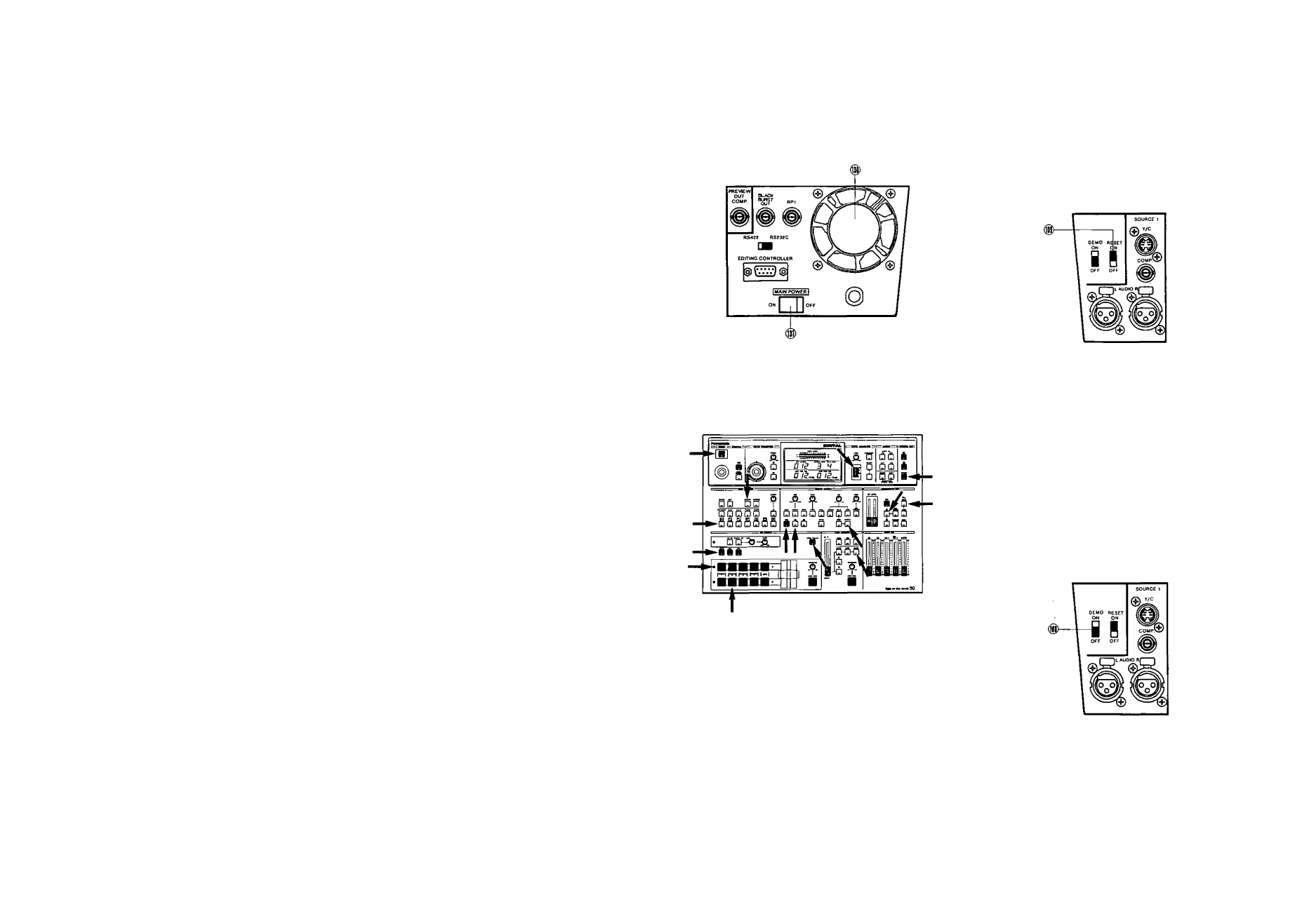
A-1. Power
1. Turn on the MAIN POWER Switch (131) located on the
rear panel. The unit is now in stand-by mode. No
operations can be executed yet.
Press the POWER Button (1) on the operation panel.
The unit is now in operation mode and the Cooling Fan
(130) located on the rear panel starts to rotate. The
LED's on the operation panel light up as shown if the
RESET Switch (109) was already in the ON position.
Notes:
1. If you do not use the unit for an extended period
ot time or to shut off the power completely, switch
off the MAIN POWER Switch (131).
If the Cooling Fan (130) does not rotate, turn off
and disconnect the AC power cord. Call service
personnel before attempting further use.
The power of WJ-MX50 can be turned on from
the Stand-by mode by turning on the power of
AG-A800. In this case the LED of the Mix Select
Button (73) turns on instead of the Wipe Select
Button (74).
2
.
3.
A-2. RESETSwitCh
1. ON position • • ■ Factory preset operation mode
It is recommended to normally keep the RESET Switch
(109) in the ON position. It would be helpful in case of
unexpected operational failure.
2.
OFF position • ■ ■ Field Preset operation mode
The status of the operation mode will be remembered
when the power of the unit is turned off. And this
status, without Still, Strobe and Special function, is
later recalled when the power is restored.
A-3. DEMO Switch
1. ON position
The preprogrammed demonstration of the built-in
Effect functions of the WJ-MX50 will be automatically
displayed on an attached video monitor.
Note:
This feature is useful for demonstrating functions
to a new user to help familiarize him/herself with
the unit.
2. OFF position
The unit reverts to standard operation mode,
switch is normally set to the OFF position.
This
A-4. Confirm that the unit is in the operation mode. Then
set up the operation panel as mentioned in the next
operating procedure.
- 16 -
- 17 -