B-3. audio mixer, B-4. color correction, B-3, audio mixer b-4. color correction – Panasonic WJ-MX50 User Manual
Page 18
Attention! The text in this document has been recognized automatically. To view the original document, you can use the "Original mode".
B-3. Audio Mixer
There are 7 audio source inputs on the WJ-MX50 -
the Source 1 /2/3/4, 2 auxiliary audio inputs (AUX1,2}
and the external microphone. Each audio level can be
adjusted independently by the audio faders.
The EFFECT Button (17) must be on to have the mixed
audio outputs as combined in Audio Mix.
• When the AUX2 audio (instead of external microphone)
is to be adjusted, turn the AUX-2/Mic Switch (105) on
the front panel to the AUX2 position.
B-4. Color Correction
This function allows for the adjustment of color from
the selected input source, as well as compensation
for excessive color. Using the monochrome effect, a
single tint can be cast over on entire scene image.
Notes:
1. The Color Correction will have no effect if the
selected source video is a Black/White signal.
The MONO Button (34) on the DIGITAL EFFECT
should be off.
The same color correction should be applied to
both the A-bus and B-bus signals.
2
.
3.
--------------lAO.—MM *1
— o
ItTo
[
u r m
LW —
--------------------------- 1
n 1 n i n 1
1 n i
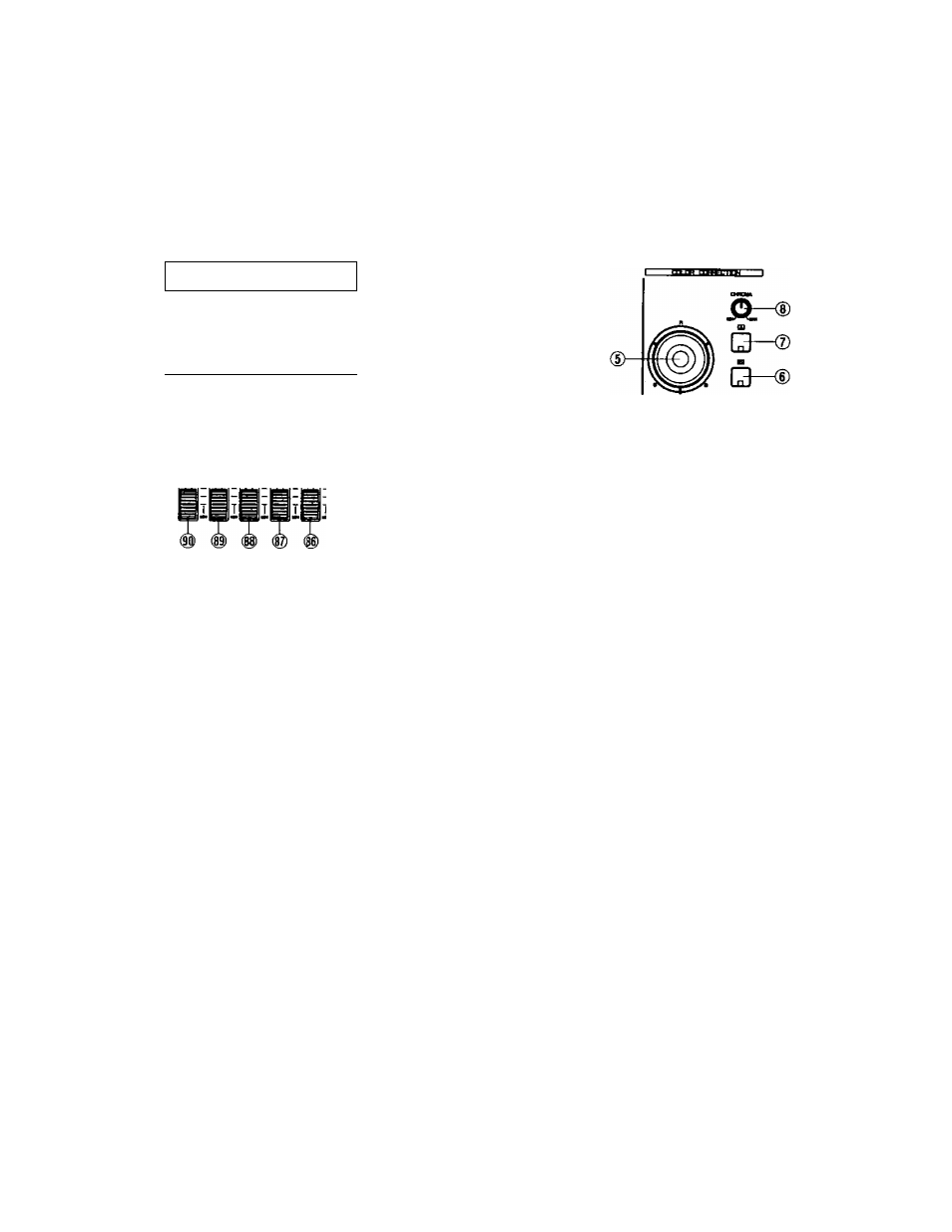
The A Fader (90) adjusts the audio level of the A-bus
Source Audio Signal; the B Fader (89) adjusts that of
the B-bus. The AUX1 Fader (88) or the MIC/AUX2
Fader (87) adjusts each respective audio input signal
accordingly.
The MASTER Fader (86) adjusts the output audio level
of the 4 mixed input faders. It is advisable to adjust
the average output audio level to about 0 dB as
represented on the Audio Level Indicator (9).
When the A Button (15) on the PROGRAM OUT
is pressed, the A-bus/AUXI /AUX2-MIC audios are
output to the Program Out Audio-1, -2 on the rear
panel.
When the B Button (16) on the PROGRAM OUT is
pressed,the B-bus/AUX1 /AUX2-MIC audios are output
to the Program Out Audio -1, -2.on the rear panel.
When the EFFECT Button (17) on the PROGRAM OUT
is pressed, A-bus/B-bus/AUX1/AUX2-MIC audios are
output ot the Program Out Audio -1,-2 on the rear panel.
To correct the A-bus signal, press the A Button (7) once.
The LED starts blinking. In this case only the CHROMA
Control (8) performs a color correction for the A-bus
signal. If you press the A Button (7) a second time,
the LED is turned on. The CHROMA Control (8) and
the R/G/B Control (5) are then available to make color
correction for the A-bus signal. To eliminate the color
correction funtion, press the A Button (7) a third time to
turn off the LED.
To correct the B-bus signal, press the B Button (6)
once. The LED starts blinking. In this case only the
CHROMA Control (8) performs color correction for the
B-bus signal. If you press the B Button (6) a second
time, the LED is turned on. The CHROMA Control (8)
and the R/G/B Control (5) are then available to make
color correction for the B-bus signal. To eliminate the
color correction, press the B Button (6) a third time to
turn off the LED.
If the CHROMA Control (8) is turned fully to the MIN
position and the position of the R/G/B Control (5) to
the center, a Black and White video image is obtained.
When adjusting the R/G/B Control (5) from this position,
a mono tone (R/G/B) video image is obtained.
Note:
The Black and White video image is obtained in
another way - Press the Color-A Button (7) or
Color-B (6) Button twice (The LED blinks). Turn the
CHROMA Control (8) to fully MIN position.
- 19 -