2 fiber optic setup, 2 fiber optic setup -2 – CANOGA PERKINS 3240S SNMP Managed Fiber Optic Multiplexer User Manual
Page 18
3240S F I B E R O P T I C M U L T I P L E X E R
3240S Fiber Optic Multiplexer
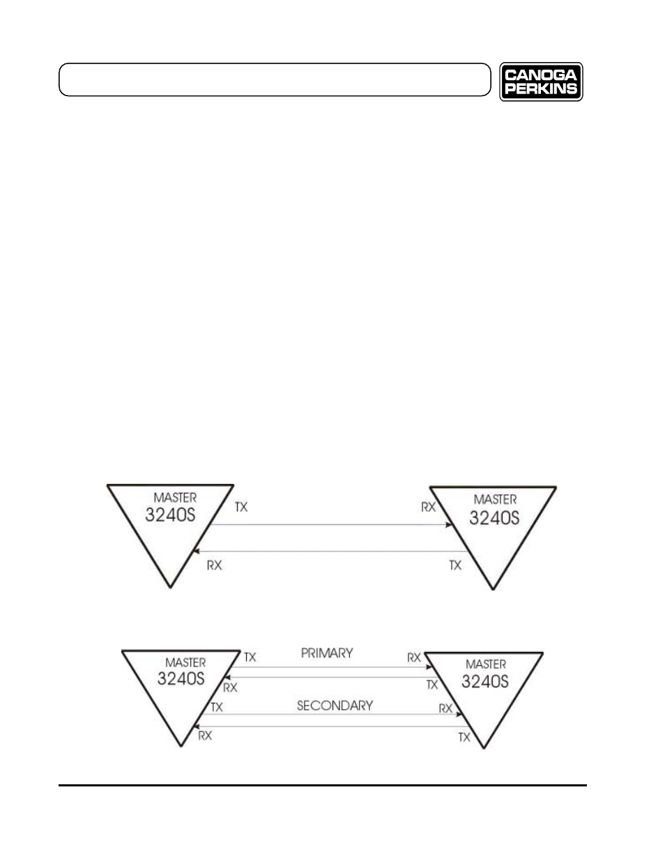
Figure 2-3
Typical Connection - Redundant Optics
Figure 2-2
Typical Connection - Non-Redundant Optics
2.2 Fiber Optic Setup
Here are a few pre-installation fiber optic check points to consider:
•
When using a fiber optic link with a loss of less than 6dB; set the optical power switch to LO. This will eliminate the
chance of saturating the receive optics at the remote end of the link. This may not be necessary if the multiplexer has
a multimode or low power laser transmitter.
•
When using a fiber optic link with a loss of more than 6dB; set the optical power switch to HI.
•
Verify the integrity of the fiber optic cables (Rx /Tx). Connect the Tx cable of unit A to the Rx connector
of unit B and vice versa.
Once you have determined the characteristics of the fiber links, connect the fiber at both ends of the multiplexer link. (See
Section 2.4 for a detailed review of Redundant Optics Operation.)
Redundant Link:
•
Local Transmit (Tx) Primary - connects to - Remote Receiver (Rx) Primary
•
Local Tx Secondary - connects to - Remote Rx Secondary
•
Remote Tx Primary - connects to - Local Rx Primary
•
Remote Tx Secondary - connects to - Local Rx Secondary
Non-redundant Link:
•
Local Tx - connects to - Remote Rx
•
Remote Tx - connects to - Local Rx
Reference Figure 2-2 for a graphical depiction of a typical non-redundant fiber optic connection. Figure 2-3 shows a typical
redundant fiber optic connection.
2-2