WEATHER GUARD Model 252-3-02 EZ-GLIDE® System, Full-Size, GM User Manual
Page 9
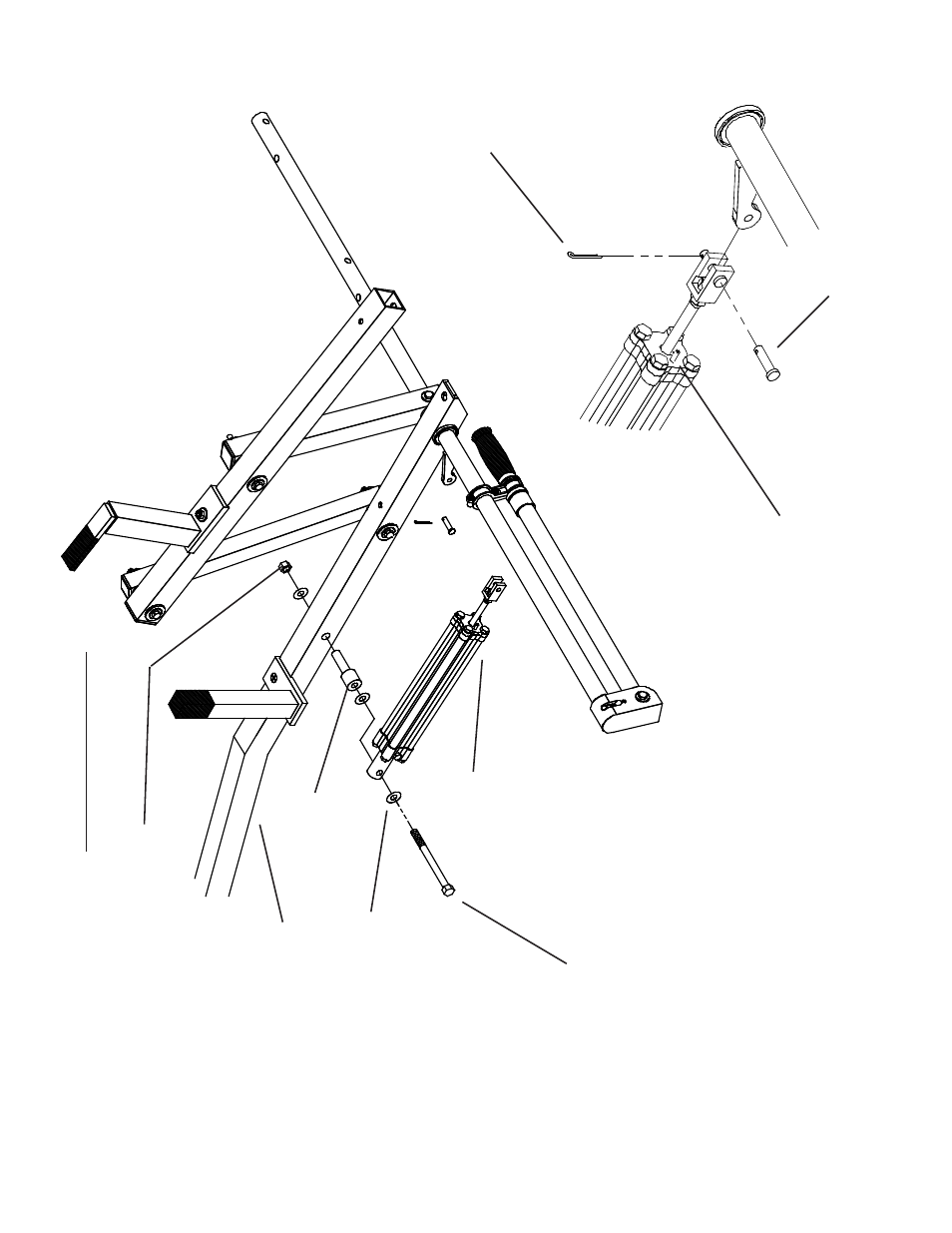
STEP 12
Attach front of Cylinder as shown. Bend over
Cotter Pin after inserting it through Clevis Pin.
CYLINDER INST
ALLA
TION
5/16-18 Nylon
Lock Nut
(3) 3/8" Flat
W
asher
5/16-18 x 4-1/2"
Hex Hd. Bolt
(A)
Cotter Pin
Clevis Pin
NO
TE:
T
urn the Flo
w Contr
ol
counter c
loc
kwise to release
pressure
. Adjust Flo
w Contr
ol
Scre
w P
er Instruction Decal
On Handle
Tube after final as
-
semb
ly and installation.
STEP 11
Insert
Aluminum Bushing (A) into Rear
Cross-Member (B).
Attach back of Cylinder (C)
to crossmember by installing 5/16-18 x 4-1/2"
Fastener
.
(C)
(B)
9
This manual is related to the following products:
See also other documents in the category WEATHER GUARD For the car:
- Model 1450 WEEKENDER® Ladder Rack, Horizontal (8 pages)
- Model 1285 FAST RACK® Accessory Cab Screen (3 pages)
- Model 1280 FAST RACK® Ladder Rack System (6 pages)
- Model 1345 Ladder Rack System, Steel, Compact, Short Bed (4 pages)
- Model 1259 Accessory Cab Screen (2 pages)
- Model 1245 Ladder Rack System, Steel, Short Bed (4 pages)
- Model 1225 Service Body Rack, Steel, Full (8 pages)
- 1211 (6 pages)
- 1205 (8 pages)
- 9036 Strong Box (2 pages)
- 644-X-01 through 685-X-01 (15 pages)
- 160-X-01 THRU 173-X-01 (4 pages)
- 178-X-01 through 181-X-01 (12 pages)
- 164-X-01 THRU 186-X-01 (18 pages)
- Model 524-3-02 Underbed Box, Steel, Standard, 4.5 cu ft (2 pages)
- 524-3-02 through 662-0-02 (9 pages)
- Model 364-0-02 Hi-Side Box, Aluminum, 7.9 cu ft (18 pages)
- 143-5-01 (12 pages)
- 114-X-01 THRU 156-X-01 (4 pages)
- 130-5-01 (12 pages)
- 126-5-02 (12 pages)
- Model 1904-3-02 PROTECT-A-RAIL® Cab Protector, Steel (4 pages)
- 1908 (2 pages)
- Model 1910-3-01 PROTECT-A-RAIL® Cab Protector, Steel (4 pages)
- Model 300 PACK RAT® Dividers (6 pages)
- 3100 (6 pages)
- Model 350-3-01 Transfer Tank, L-Shape, 50 gal (4 pages)
- Model 1246 Airfoil, Ford Super Duty (2 pages)
- 201 (1 page)
- 200 (2 pages)
- Model 239 Conduit Carrier Kit (2 pages)
- 237 (4 pages)
- Model 114-0-01 Cross Box, Aluminum, Full Extra Wide, 15.3 cu ft (4 pages)
- Model 160-3-01 Pork Chop Box, Steel, Driver Side, 2.1 cu ft (4 pages)
- Model 246-3-02 Hi-Side Box, Steel, 5.6 cu ft (2 pages)
- Model 346-0-02 Hi-Side Box, Aluminum, 11.8 cu ft (2 pages)
- Model 1060-5 FAST RACK® Accessory Cross Member (1 page)
- Model 1908 PROTECT-A-RAIL® Heavy Duty Cab Protector, Steel (2 pages)
- Model 3100 BED RAT® Sliding Platform, 54 in x 22 in x 4-3/4 in (6 pages)
- Model 314-3 ITEMIZER® Drawer Unit, Lateral, 49 in x 12-1/4 in x 6-3/4 in (3 pages)
- Model 9020-3-01 Lockable Cabinet, No Shelf, 22 in x 18 in x 16 in (9 pages)
- Model 96101-3-01 Window Bulkhead, Full-Size, Ford, GM (24 pages)
- Model 96111-3-01 Mesh Bulkhead, Compact, Ford Transit Connect (12 pages)
- Model 96111-3-02 Mesh Bulkhead, Compact, 2014 Ford Transit Connect (4 pages)
- Model 96115-3-01 Mesh Bulkhead, Compact, RAM CV (4 pages)