Pilz PSEN sl-1.0fm 1unit User Manual
Page 3
- 3 -
1487029387
1. Am Meldeausgang liegt ein High-Signal an,
wenn der Betätiger im Ansprechbereich ist
(Schutztür geschlossen). Der Meldeausgang
bleibt high, wenn
– an den Eingang S31 ein High-Signal ange-
legt wird (Zuhaltemagnet eingeschaltet)
und
– die Zuhaltekraft innerhalb von t
lock
(600
ms) aufgebaut werden konnte.
2. Der Meldeausgang wechselt nach low, wenn
der Aufbau der Zuhaltekraft t
lock
(600 ms)
überschreitet. Aus diesem Zustand kann der
Meldeausgang nur dann wieder nach high
wechseln, wenn am Eingang S31 erst ein
Low- und danach ein High-Signal angelegt
wird.
3. Der Meldeausgang wechselt nach low, wenn
der Betätiger den Ansprechbereich verlässt
(Schutztür geöffnet).
1090038795
Magnetische Zuhaltung und Magnet-
überwachung
Der Zuhaltemagnet wird eingeschaltet, wenn
S31 high ist und der Betätiger erkannt wird
(Schutztür geschlossen).
Die Haltekraft des Zuhaltemagneten wird
beim Einschalten getestet. Wenn dieser Test
erfolgreich abgeschlossen ist, wechseln die
Sicherheitsausgänge in den High-Zustand.
Wird am eingeschalteten Zuhaltemagneten
Windungsunterbruch, oder Windungskurz-
schluss erkannt, wechseln die Sicherheitsaus-
gänge 12 und 22 in den Low-Zustand.
INFO
Wenn die Schutztür im zugehaltenen Zu-
stand gewaltsam geöffnet wird, schalten
die Sicherheitsausgänge ab.
1. There is a high signal at the signal output
when the actuator is within the response ran-
ge (safety gate closed). The signal output
remains high if
– a high signal is present at the input S31
(locking magnet switched on)
and
– the holding force could be built up within
t
lock
(600 ms).
2. The signal output switches to low when the
build-up of the holding force exceeds t
lock
(600 ms). From this status the signal output
can only switch to high again when a low and
then a high signal is present at the input S31.
3. The signal output switches to low when the
actuator leaves the response range (safety
gate open).
Magnetic guard locking device and ma-
gnet monitoring
The locking magnet is switched on if S31 is
high and the actuator is detected (safety gate
closed).
The holding force of the locking magnet is
tested on power-up. If this test is completed
successfully, the safety outputs switch to a
high state.
If an open winding or a winding short circuit is
detected on a locking magnet that is switched
on, safety outputs 12 and 22 switch to a low
state.
INFORMATION
If the safety gate is in a locked condition
and is opened by force, the safety outputs
will shut down.
1. La sortie de signalisation est à « 1 » si l'ac-
tionneur se trouve dans la zone de détection
(protecteur mobile fermé). La sortie de signa-
lisation reste à « 1 » si
– l'entrée S31 est à « 1 » (aimant d'interver-
rouillage activé)
et si
– la force d'interverrouillage est créée en
l'espace de t
lock
(600 ms).
2. La sortie de signalisation passe à « 0 » si la
force d'interverrouillage dépasse t
lock
(600 ms). À partir de cet état, la sortie de si-
gnalisation ne peut alors passer à « 1 » que si
l'entrée S31 est d'abord à « 0 » puis à « 1 ».
3. La sortie de signalisation passe à « 0 » si l'ac-
tionneur quitte la zone de détection (protec-
teur mobile ouvert).
Interverrouillage magnétique et surveil-
lance magnétique
L'aimant d'interverrouillage est activé si S31
est à l'état « 1 » et si l'actionneur est détecté
(protecteur mobile fermé).
La force d'interverrouillage de l'aimant est
testée lors de l'activation. Si ce test a été ef-
fectué avec succès, les sorties de sécurité
passent à l'état « 1 ».
Si une coupure de la bobine ou un court-circuit
de la bobine est détecté sur l'aimant d'interver-
rouillage activé, les sorties de sécurité 12 et 22
passent à l'état « 0 ».
INFORMATION
Si le protecteur mobile en position fermée
est ouvert par la force, les sorties de sécu-
rité sont désactivées.
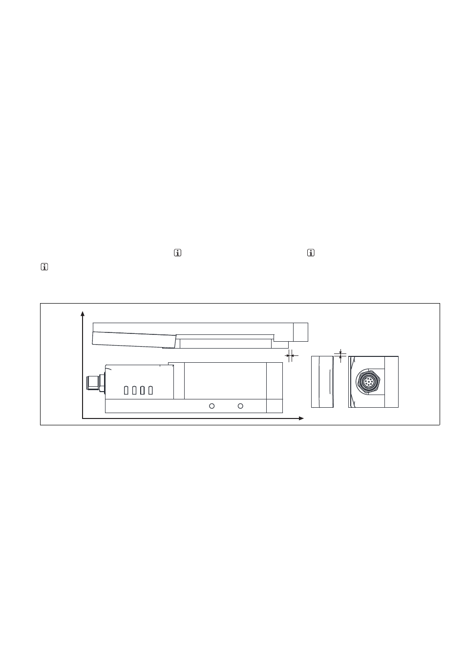
Seiten- und Höhenversatz
Lateral and vertical offset
Décalage latéral et en hauteur
1077141515
Höhenversatz max. 5 mm
Seitenversatz max. 3 mm
Vertical offset max. 5 mm
Lateral offset max. 3 mm
Décalage en hauteur max. 5 mm
Décalage latéral max. 3 mm
Verdrahtung
1460809099
Beachten Sie:
Angaben im Abschnitt "Technische Daten"
unbedingt einhalten.
Wiring
Please note:
Information given in the "Technical details"
must be followed.
Raccordement
Important :
Respecter impérativement les données indi-
quées dans le paragraphe « Caractéristiques
techniques ».
Hinweise zur Leitungslänge
1460805899
Die max. Leitungslänge ist abhängig vom
Spannungsabfall an den Leitungen zum Sen-
sor. Die Höhe des Spannungsabfalls wird be-
stimmt durch:
den Leitungswiderstand
den Strom des Gerätes und der Strombela-
stung der Sicherheitsausgänge 12 und 22
Wird die minimal zulässige Versorgungsspan-
nung am Stecker des Geräts unterschritten
(s. technische Daten), wird der Elektromagnet
nicht mehr zuverlässig angesteuert. Die LED
"Lock" meldet einen Fehler bei der Zuhaltung.
Guidelines for cable length
The max. cable length depends on the voltage
drop at the sensor cables. The level of voltage
drop is determined by the:
Cable resistance
Current of the device and the current load of
the safety outputs 12 and 22
If the level of the supply voltage at the device
connector falls below the minimum permitted
value (see Technical details), the electromagnet
is no longer activated reliably. The "Lock" LED
registers an error when guard locking.
Remarques concernant la longueur des câ-
bles
La longueur maximale des câbles dépend de la
chute de tension dans les câbles utilisés pour le
capteur. Le niveau de la chute de tension est
déterminée par :
la résistance du câble
le courant de l'appareil et la charge électri-
que des sorties de sécurité 12 et 22.
Si la tension d'alimentation minimale autorisée
est inférieure au connecteur de l'appareil (voir
les caractéristiques techniques), l'aimant élec-
trique n'est plus commandé en toute fiabilité.
La LED « Lock » signale une erreur lors de l'in-
terverrouillage.
Lock
Safety Gate
Power Fault
Input
Seitenversatz/Lateral offset/
Décalage latéral
Höhenversatz/Vertical offset/Décalage vertical