Safety gate s31 guard locking y32 – Pilz PSEN sl-1.0fm 1unit User Manual
Page 2
- 2 -
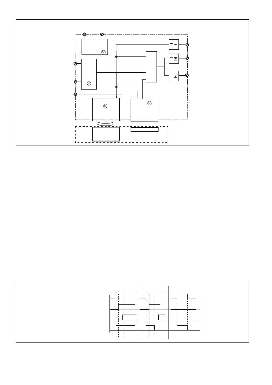
Blockschaltbild
Block diagram
Schéma de principe
Funktionsbeschreibung
1486993931
Sicherheitsausgänge
An den Sicherheitsausgängen 12 und 22 liegt
ein High-Signal, wenn gleichzeitig:
der Betätiger im Ansprechbereich ist.
(Schutztür geschlossen) und
die Eingänge S11 und S21 high sind und
der Eingang S31 high ist (Steuerbefehl für
magnetische Zuhaltung) und der Zuhaltema-
gnet eingeschaltet ist.
Die Sicherheitsausgänge 12 und 22 sind low,
wenn:
Der Betätiger sich außerhalb des Ansprech-
bereichs befindet oder
die Eingänge S11 und S21 low sind oder
der Eingang S31 low ist (Steuerbefehl für ma-
gnetische Zuhaltung) und der Zuhaltemagnet
ausgeschaltet ist
Wurden die Sicherheitsausgänge durch einen
der Eingänge S11 oder S21 abgeschaltet, dann
ist ein Wiedereinschalten nur möglich, nach-
dem beide Eingänge gleichzeitig low waren.
Die Sicherheitseingänge S11 und S21 werden
auf Plausibilität überwacht. Beide Eingänge
müssen gemeinsam aus- und einschalten (Teil-
betätigungssperre).
1487004043
Meldeausgang
Der Meldeausgang Y32 meldet, ob der Betäti-
ger im Ansprechbereich ist und ob die Halte-
kraft des Zuhaltemagneten nach 600 ms
erreicht wurde.
Function description
Safety outputs
There is a high signal at safety output 12 and 22
if the following occur simultaneously:
The actuator is within the response range
(safety gate closed) and
Inputs S11 and S21 are high and
Input S31 is high (control command for mag-
netic guard locking) and the locking magnet
is switched on.
Safety outputs 12 and 22 are low if:
The actuator is outside the response range or
Inputs S11 and S21 are low or
Input S31 is low (control command for mag-
netic guard locking) and the locking magnet
is switched off.
If the safety outputs have been shut down by
either of the inputs S11 or S21, they cannot be
switched back on until both inputs are low si-
multaneously.
Safety inputs S11 and S21 are monitored for
feasibility. Both inputs must switch off and on
together (partial operation lock).
Signal output
The signal output Y32 signals whether the ac-
tuator is within the response range and whether
the holding force of the locking magnet has
been achieved after 600 ms.
Description du fonctionnement
Sorties de sécurité
Les sorties de sécurité 12 et 22 sont à « 1 » si,
simultanément :
l'actionneur se situe dans la zone de détec-
tion. (protecteur mobile fermé) et
les entrées S11 et S21 sont à « 1 » et
l'entrée S31 est à « 1 » (ordres de commande
avec interverrouillage magnétique) et
l'aimant d'interverrouillage est activé.
Les sorties de sécurité 12 et 22 sont à « 0 » si :
l'actionneur se trouve à l'extérieur de la zone
de détection ou si
les entrées S11 et S21 sont à « 0 » ou
l'entrée S31 est à « 0 » (ordres de commande
avec interverrouillage magnétique) et
l'aimant d'interverrouillage est désactivé.
Si les sorties de sécurité sont coupées par l'une
des entrées S11 ou S21, un redémarrage est
uniquement possible dès que les deux entrées
ont йtй а « 0 » en même temps.
La plausibilité des entrées de sécurité S11 et
S12 est surveillée. Les deux entrées doivent
être mises hors tension et sous tension simul-
tanément (activation partielle).
Sortie de signalisation
La sortie de signalisation Y32 signale si l'ac-
tionneur se trouve dans la zone de détection et
si la force d'interverrouillage de l'aimant d'inter-
verrouillage a été atteinte après 600 ms.
Y32
S11
22
Empfänger
Receiver
Récepteur
Betätiger
Actuator
Actionneur
A1
A2
U
B
S21
12
Netzteil
Power supply
Alimentation
S31
Magnet
Magnet
Aimant
&
Input
&
Safety Gate
&
Power / Fault
Lock
Safety gate
S31
Guard locking
Y32
closed
open
active
not active
high
low
t
lock
t
lock
high
low