Pilz PSEN cs1.19 1sw+OSSD2 User Manual
Page 4
- 4 -
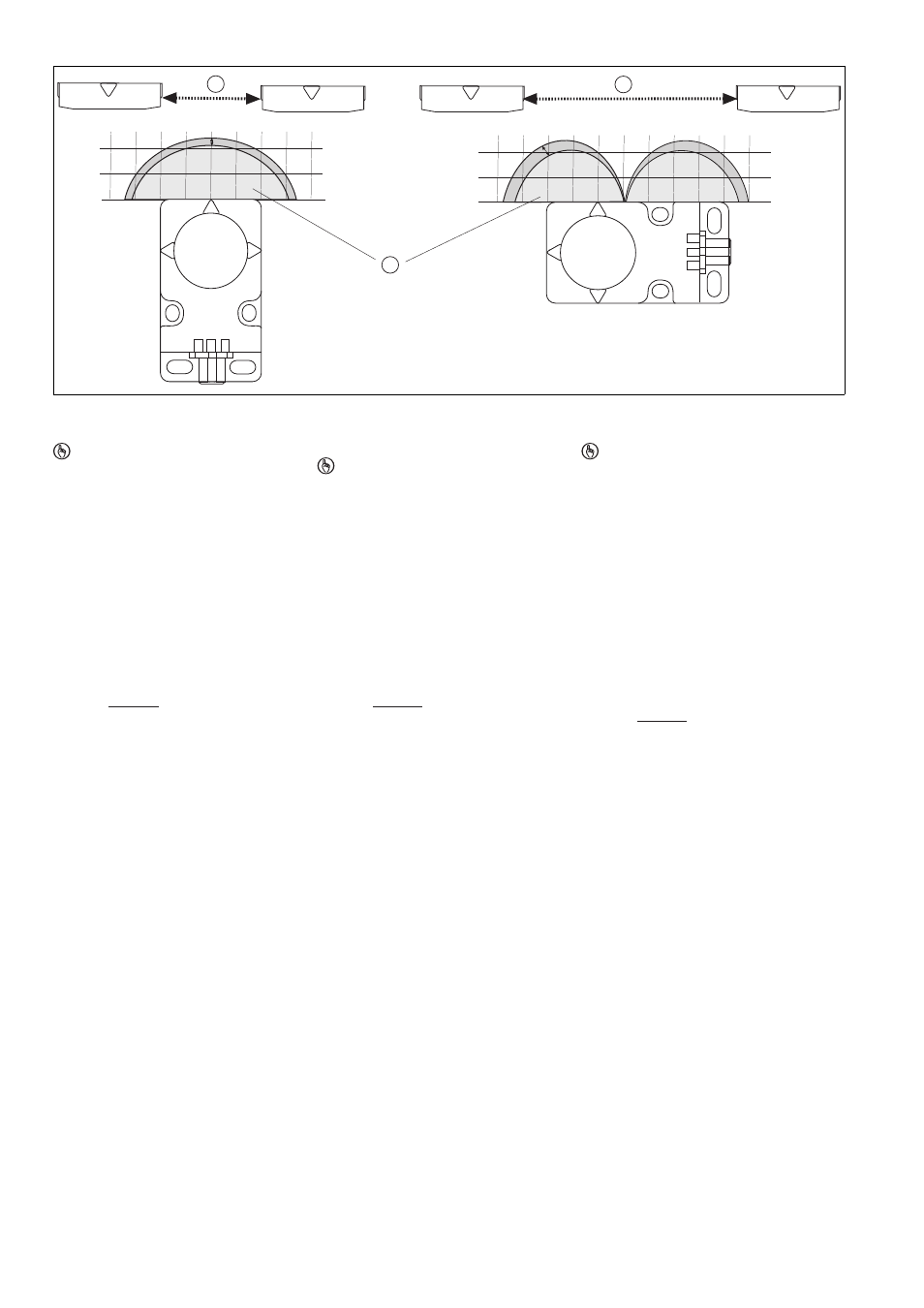
Abstand zwischen Betätigern
Distance between actuators
Distance entre les actionneurs
1388764683
: Min. Abstand zwischen 2 Betätigern: bei
Betätigungsrichtung frontal/seitlich
: Ansprechbereich
WICHTIG
Damit die Betätiger fehlerfrei erkannt wer-
den, muss
beim Anfahren der Betätiger in den An-
sprechbereich zwischen 2 Betätigern ein
zeitlicher Abstand eingehalten werden,
die max. Anfahrgeschwindigkeit einge-
halten werden.
Die Werte entnehmen Sie bitte den technischen
Daten.
: Min. distance between 2 actuators when
the direction of actuation is from the front/
side
: Response range
NOTICE
To detect the actuator without error, it is
necessary to maintain
an interval when approaching the actua-
tors into the response range between 2
actuators,
the max. approach speed.
For the values please refer to the technical de-
tails.
: distance min. entre 2 actionneurs : avec
un sens de manœuvre frontal / latéral
: zone de détection
IMPORTANT
Afin que l'actionneur puisse être parfaite-
ment détecté, il faut
respecter un intervalle de temps entre 2
actionneurs lors de l'approche de l'ac-
tionneur dans la zone de détection ;
respecter la vitesse d'approche maxima-
le.
Les valeurs sont indiquées dans les caractéris-
tiques techniques.
Verdrahtung
517049611
Beachten Sie:
Angaben im Abschnitt „Technische Daten“
unbedingt einhalten.
Berechnung der max. Leitungslänge I
max
im
Eingangskreis:
R
lmax
= max. Gesamtleitungswiderstand
(s. techn. Daten)
R
l
/ km = Leitungswiderstand/km
Wiring
Please note:
Information given in the “Technical details”
must be followed.
Calculation of the max. cable length l
max
in
the input circuit:
R
lmax
= max. overall cable resistance (see
Technical details)
R
l
/ km = cable resistance/km
Raccordement
Important :
Respectez impérativement les données indi-
quées dans la partie "Caractéristiques tech-
niques".
Calcul de la longueur de câble max. I
max
sur
le circuit d'entrée :
R
lmax
= résistance max. de l'ensemble du
câblage (voir les caractéristiques techni-
ques)
R
l
/ km = résistance du câblage/km
0
10
20
0 1 0 20 30 40
-10
-20
-30
-40
0
10
20
Power /Fault
OSSD1
OSSD2
Schaltabstand in mm
0
10
20
0 10 20 30 40 50 60
-10
-20
-30
-40
0
10
20
Power /Fault
OSSD1
OSSD2
1
2
1
R
lmax
R
l
/ km
I
max
=
R
lmax
R
l
/ km
I
max
=
R
lmax
R
l
/ km
I
max
=