Pilz PSEN cs1.19 1sw+OSSD2 User Manual
Pilz Sensors
22195-3FR-02
PSEN cs1.19n
- 1 -
4
D
Betriebsanleitung
4
GB Operating instructions
4
F
Manuel d'utilisation
22195-3FR-02
PSEN cs1.19n
Sicherheitsschalter PSEN cs1.19n
1379279755
Der Sicherheitsschalter erfüllt die Anforderun-
gen nach:
EN 60204-1
EN 60947-5-3: PDF-M zusammen mit dem
Betätiger (siehe technische Daten).
EN 62061: bis max. SIL CL 3 (s. sicherheits-
technische Kenndaten)
EN ISO 13849-1: 2006: bis max. PL e (s. si-
cherheitstechnische Kenndaten)
Der Sicherheitsschalter darf nur mit den zu-
gehörigen Betätigern OSSD1, OSSD2,
OSSD1&2 verwendet werden.
Safety switch PSEN cs1.19n
The safety switch meets the requirements in
accordance with:
EN 60204-1
EN 60947-5-3: PDF-M in conjunction with
the actuator (see Technical Details).
EN 62061: up to max. SIL CL 3 (see safety-
related characteristic data)
EN ISO 13849-1: 2006: up to max. PL e (see
safety-related characteristic data)
The safety switch may only be used with the
corresponding actuators OSSD1, OSSD2,
OSSD1&2.
Capteur de sécurité PSEN cs1.19n
Le capteur de sécurité satisfait aux exigences
des normes :
EN 60204-1
EN 60947-5-3 : PDF-M avec l'actionneur
(voir les caractéristiques techniques).
EN 62061 : max. jusqu'au SIL CL 3 (voir les
caractéristiques techniques de sécurité)
EN ISO 13849-1:2006 : max. jusqu'au PL e
(voir les caractéristiques techniques de sé-
curité)
Le capteur de sécurité doit être utilisé uni-
quement avec les actionneurs correspon-
dants OSSD1, OSSD2, OSSD1&2.
Zu Ihrer Sicherheit
547263243
Installieren und nehmen Sie das Gerät nur
dann in Betrieb, wenn Sie diese Betriebsan-
leitung gelesen und verstanden haben und
Sie mit den geltenden Vorschriften über Ar-
beitssicherheit und Unfallverhütung vertraut
sind.
Beachten Sie die VDE- sowie die örtlichen
Vorschriften, insbesondere hinsichtlich
Schutzmaßnahmen
Durch Öffnen des Gehäuses oder eigen-
mächtige Umbauten erlischt jegliche Ge-
währleistung.
777809547
Entfernen Sie die Schutzkappe erst unmittel-
bar vor Anschluss des Geräts.
For your safety
Only install and commission the unit if you
have read and understood these operating
instructions and are familiar with the applica-
ble regulations for health and safety at work
and accident prevention.
Ensure VDE and local regulations are met,
especially those relating to safety.
Any guarantee is rendered invalid if the hous-
ing is opened or unauthorised modifications
are carried out.
Do not remove the protective cap until you
are just about to connect the unit.
Pour votre sécurité
Vous n'installerez l'appareil et ne le mettrez
en service qu'après avoir lu et compris le
présent manuel d'utilisation et vous être fa-
miliarisé avec les prescriptions en vigueur
sur la sécurité du travail et la prévention des
accidents.
Respectez les normes locales ou VDE, parti-
culièrement en ce qui concerne la sécurité.
L'ouverture de l'appareil ou sa modification
annule automatiquement la garantie.
Veuillez retirer le cache de protection avant
de raccorder l'appareil.
Gerätemerkmale
1381122699
Transpondertechnik
2 Sicherheitsausgänge
3 Betätiger
LED-Anzeige für:
– aktiven Betätiger
– Versorgungsspannung/Fehler
4 Betätigungsrichtungen
5-poliger M12 Stiftstecker
Codierung: codiert
Unit features
Transponder technology
2 safety outputs
3 actuators
LED for:
– Active actuator
– Supply voltage/fault
4 actuation directions
5 pin M12 male connector
Coding: coded
Caractéristiques de l'appareil
Technique à transpondeur
2 sorties de sécurité
3 actionneurs
LEDs de visualisation pour les états
suivants :
– actionneurs actifs
– tension d'alimentation / erreurs
4 sens de manœuvre
Connecteur mâle M12 à 5 broches
Codage : codé
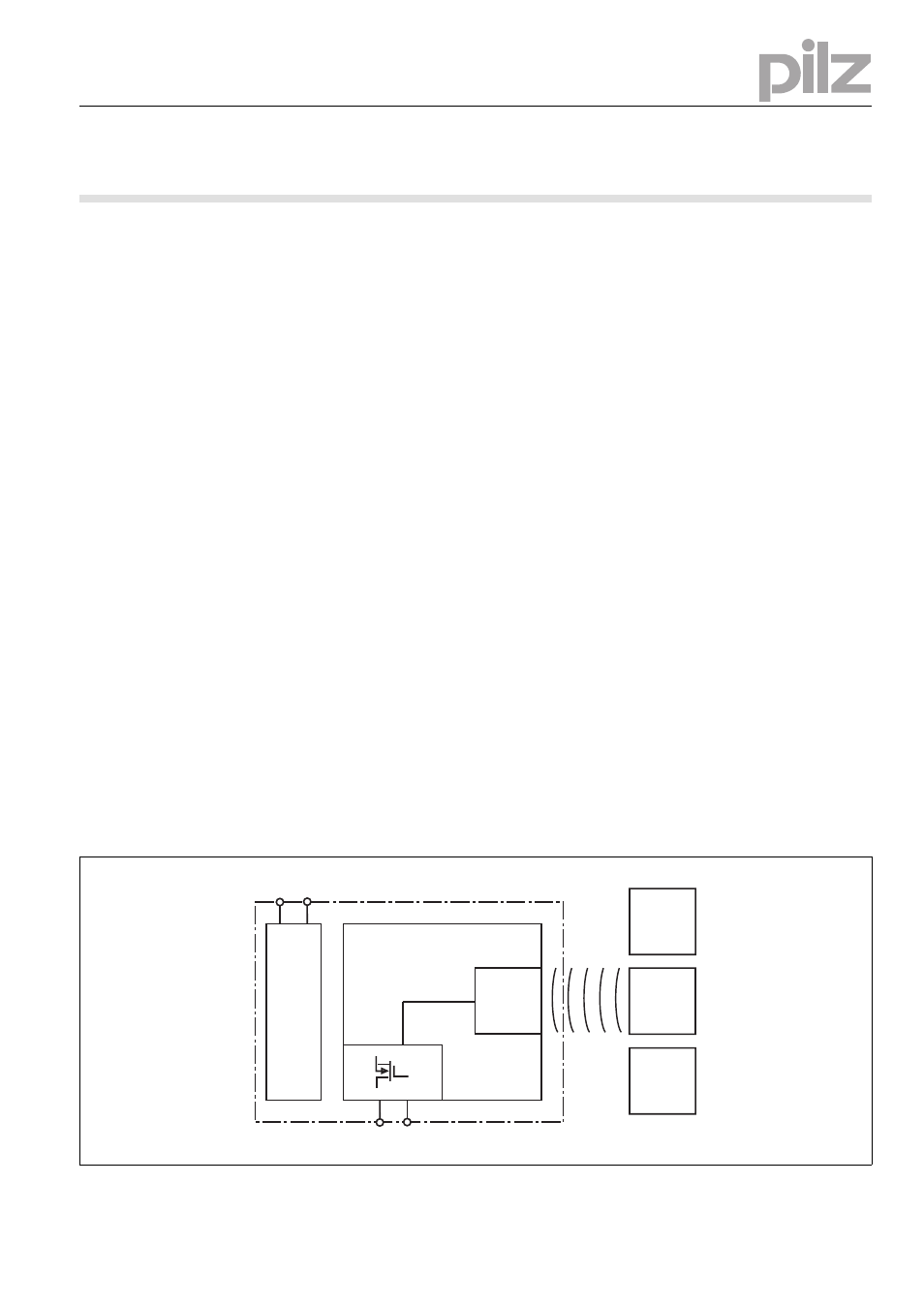
Blockschaltbild
Block diagram
Schéma de principe
A1 A2
Power
12 22
Receiver
Actuator
OSSD1
Actuator
OSSD1&2
Actuator
OSSD2