B&C Technologies SA Series Industrial User Manual
Page 17
INSTALLATION PROCEDURES
3-5
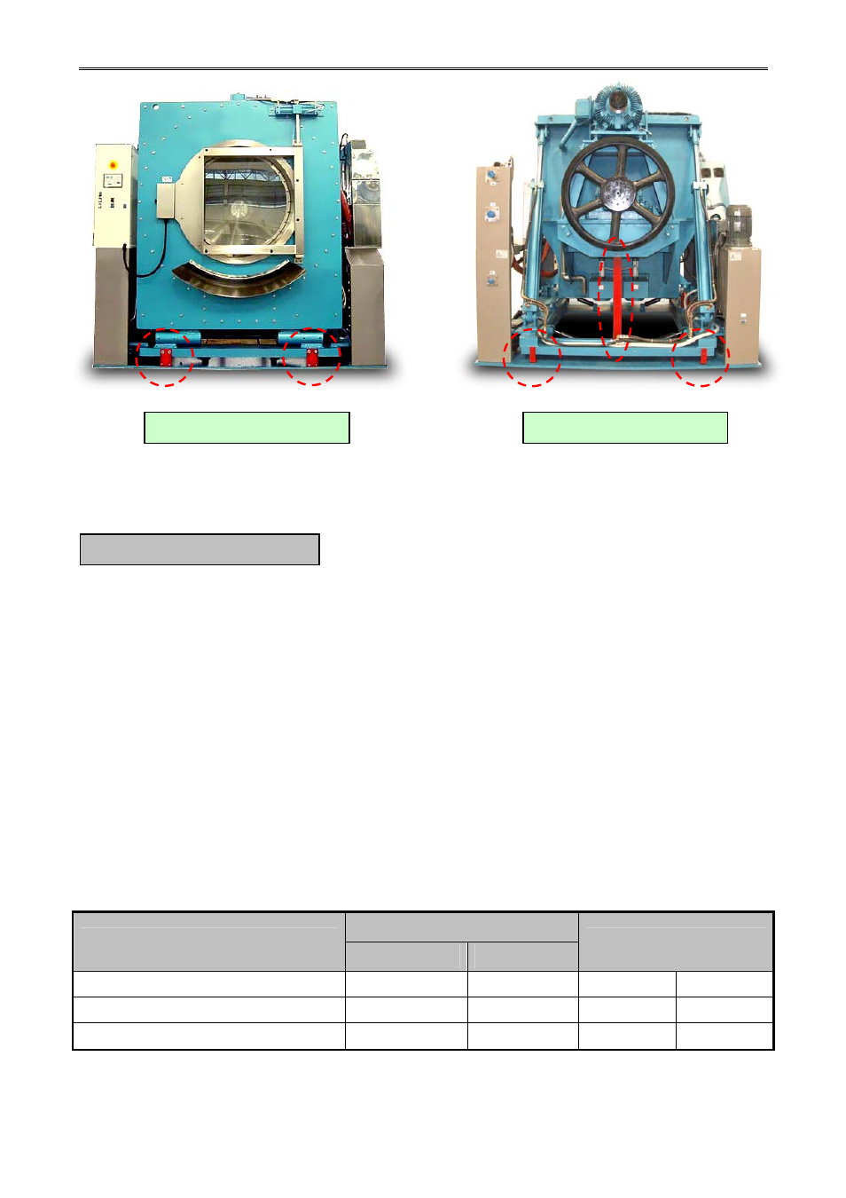
Figure.3-5 Location of transportation brackets inside the machine
A drain system of adequate capacity is essential to the machine performance. Ideally the
water should empty through a 4 inches vented pipe directly into a sump or floor drain.
A flexible connection must be made to a vented drain system to prevent an airlock or siphon
effect. If proper drain size is not available or practical, a surge tank is required. A surge tank in
conjunction with a sump pump should be used when gravity drainage is not possible, such as in
below – ground – level installations.
Before any deviation from specified installation procedures is attempted, the customer or
installer should contact the manufacturer. Increasing the drain hose length, installing elbows, or
causing bends will decrease drain flow rate and increase drain time, impairing machine
performance. If the drain arrangement is inadequate, the machine will not extract and will not
discharge water properly.
See table below for specific drain information.
Table.3-3 Drain Sizing
Units
Detail
Metric
US
SA Series
Drain connection Size
mm.
in
215
8 1/2
Drain flow capacity
liters / min
g.p.m.
-
-
Minimum drain it size
liters
gal
-
-
D. DRAIN CONNECTION
Front side the machine
Rear side the machine