9 connector pin-outs, color codes, 10 .error messages – Rice Lake Combination System - Precision Loads On-Board Weighing Systems User Manual
Page 59
Service and Troubleshooting
55
5.9
Connector Pin-outs, Color Codes
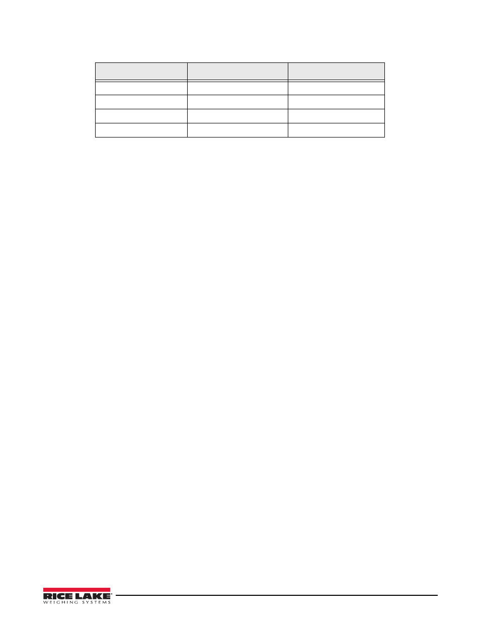
Table 5-1. Color Codes
4-Pin Connector
7-Pin Connector
3-Pin Connector
A=RED=Excitation+
A=WHITE=Signal-
A=WHITE
B=GREEN=Signal+
F=GREEN=Signal+
B=Jumpered to C
C=WHITE=Signal-
C=BLACK=Exc-
C=BLACK
D=BLACK=Excitation-
D=RED=Exc+
For systems using the Interlink connector system, please contact Rice Lake Weighing Systems for assistance.
5.10 .Error Messages
Ch.1 Red side defective
The red-banded wire may be damaged between the load cell and the channel 1 transmitter.
• The load cell connected to the red-banded wire of channel 1 may be defective.
• Swap the two load-cell cables. If the message is the same, the red-banded wire is damaged, possibly pinched
or cut. If the message changes to read the black side is defective, then the load cell is the problem.
Ch.1 Blk side defective
The black wire may be damaged between the load cell and the channel 1 transmitter.
• The load cell connected to the black wire of channel 1 may be defective.
• Swap the two load-cell cables. If the message is the same, the black wire is damaged, possibly pinched or
cut. If the message changes to say the red side is defective, then the load cell is the problem.
Ch.2 Red side defective
The red-banded wire may be damaged between the load cell and the channel 2 transmitter.
• The load cell connected to the red-banded wire of channel 2 may be defective.
• Swap the two load-cell cables. If the message is the same, the red-banded wire is damaged, possibly pinched
or cut. If the message changes to read the black side is defective, then the load cell is the problem.
Ch.2 Blk side defective
The black wire may be damaged between the load cell and the channel 2 transmitter.
• The load cell connected to the black wire of channel 2 may be defective.
• Swap the two load-cell cables. If the message is the same, the black wire is damaged, possibly pinched or
cut. If the message changes to say the red side is defective, then the load cell is the problem.
Ch.1 not connected
Channel 1 is not connected to its transmitter.
• The channel 1 wire may have been disconnected at the back of the indicator.
• The channel 1 wire may be damaged between the channel 1 transmitter and the indicator. Disconnect the
channel 1 wires from the indicator. Assuming channel 2 is working, connect the channel 2 wires to the
channel 1 terminals. If the message stays the same, the indicator is defective. If the message goes away and
channel 1 works again, then the wire is the problem. Check for a cut wire or a connector unplugged.
Ch.2 not connected
Channel 2 is not connected to its transmitter.
• The channel 2 wire may have been disconnected at the back of the indicator.
• The channel 2 wire may be damaged between the channel 2 transmitter and the indicator. Disconnect the
channel 1 wires from the indicator. Assuming channel 1 is working, connect the channel 2 wires to the
channel 1 terminals. If the message stays the same, the indicator is defective. If the message goes away and
channel 2 works again, then the wire is the problem. Check for a cut wire or a connector unplugged.