Rice Lake Combination System - Precision Loads On-Board Weighing Systems User Manual
Page 51
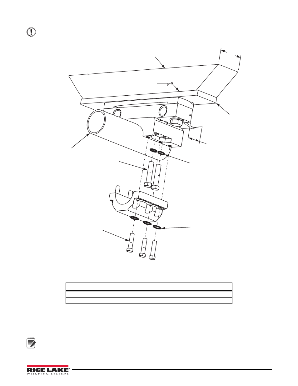
Underside Trailer Mount
4.50
Min
Ø 4.00
Trunnion
Tube
4X Torque Bolt
to 380 ft/lbs
6X Torque Bolt
to 190 ft/lbs
Anti-rotation Plate
Anti-rotation Plate
2.62
4.5 x 17.5 x .75
1018 CRS
Bend tabs up on hex flat
after final assembly.
3/16
Important
Applications
47
Do not weld the bearing plates while they are attached to the load cells as this may result in damage to
the load cell from overheating or arcing on the load cell. Improper grounding of weld current may also
destroy load cells, so they must be completely removed for final welding. See “Welding Specifications” on
page 59.
Figure 4-46. Final Assembly
Table 4-4. Specifications
Bolt Size
1-1/8" -12 UNF x 3.25"L Bolt
1000 to 1200 lb/ft. (1355-1626 Nm)
Clamp Bolts and Locknuts
380 to 420 lb/ft (542 to 600 Nm)
CONNECTIONS
1. Connect the trailer transmitter leads (2) to the load cell connectors.
Note
The transmitter has a RED lead (with red heat shrink tubing) and a BLACK lead (no heat shrink, which identifies
the load cell for diagnostics testing in the meter program).
2. Mount the transmitter in a protected area of the trailer under structure.