7 body rest mounts, 1 installation procedure, Installation procedure – Rice Lake Combination System - Precision Loads On-Board Weighing Systems User Manual
Page 41
Applications
37
Hoist Load Pin
1. Remove any existing collar when installing hoist load pin, and replace with the collar provided. Use the
load pin for locating and aligning pin and collar position, tack weld the collar in place, remove load pin and
final weld the collar per instructions.
2. Install bolt and locknut. Observe the "UP" notation stamped on the end of the hoist pin. Ensure the shear
grooves in each end of the pin overlap both sides of the mounting hardware (cheek plates and cylinder).
4.7
Body Rest Mounts
For installations of on-board systems on tipping bodies or hoist chassis which require live weighing, as opposed to
Lift-to-Weigh applications, body-rest load cell installations are required. Rice Lake Weighing Systems typically
supplies body rest kits in four or six point configurations, with two load pins typically installed at the rear hinge
pivots. The front two (or four) load cells used for body rest mounting utilizing Groove-Lock hardware is typically
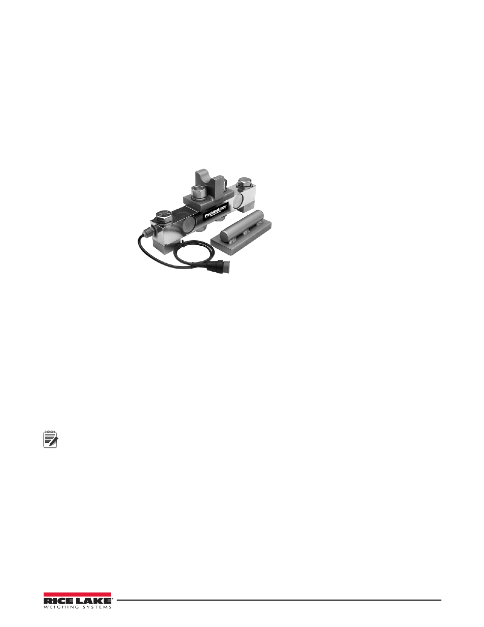
the model PL9000-14.4 shear beam load cell.
Figure 4-37. Body Rest Mount Kit for Live Weigh Applications
The kits are furnished with groove lock hardware components as shown in Figure 4-37.
4.7.1
Installation Procedure
1. Install the pivot pins at the rear hinge points as instructed in “Hinge and Hoist Pivot Pin Installation” on
page 32, except the hinge pivot bracket is removed and a 3/4" (19 mm) or 1" (25 mm) spacer is installed on
each side to elevate the body or hoist chassis subframe, off of the main chassis rails.
2. Position 2 or 4 spacer blocks of 3/4" or 1" thickness at the desired load cell positions at the front (and
middle if a six point) of the body or hoist chassis subframe. The entire subframe should now be off the
main chassis, equally on all sides.
Note
Any remaining pressure in the lift cylinder(s) should be bled off.
3. Locate and mark positioning for the load cell mounts on each side of the chassis and body or hoist
subframe rails.
4. Clamp chassis angles to the truck frame rails on each side in the desired locations (front and center
mounts). Location of the chassis bracket should avoid and rotation or movement of the lift cylinders from
relaxed to fully upright position, as well as chassis-mounted items that are not easily moved, and should
attempt to utilize as many preexisting chassis bolt holes as possible (to minimize the drilling of new holes).