Rice Lake Combination System - Precision Loads On-Board Weighing Systems User Manual
Page 43
Applications
39
11. Clamp the body angles to the subframe.
12. Remove the load cells for final welding. Final weld the body angles to the body subframe.
13. Once all welds have cooled, remount the load cells and Groove Lock hardware at each location. Use a
serviceable thread locker on all bolt threads used to bolt the Groove Lock plate assembly into the load cell,
and to bolt the load cells into the bearing plates. Torque all bolts to specification.
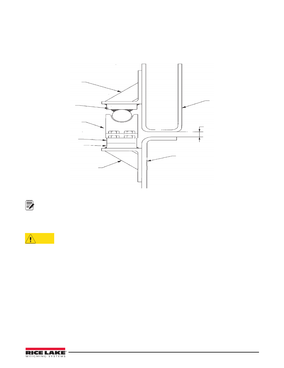
Figure 4-40. Groove Lock End View Showing PL9000-14 Load Cell
Rice Lake Weighing Systems recommends that load cell cables face inwards if possible, to provide better
protection. If the load cell output cables cannot face inwards, Rice Lake Weighing Systems recommends a
protective cover plate be welded to the chassis angle which provides protection to the cable and that split
loom, spiral wrap, split fuel line or other protection be fit to the load cell cables.
14. Remove all spacer blocks. Body subframe should rest on all load cells with Groove Lock hardware
centered on load cells. Raise and lower body to verify proper alignment and seating.
Installer must ensure that the hoist cylinder(s) do not retain pressure in the down (relaxed) position as that
will pull on the body rest load cells and affect the weight readings. All cylinder pressure must be relieved
when cylinders are relaxed and load cells are weighing load. Slow, creeping weight changes are a sign
that pressure may still be present in the lift cylinder(s). For example, in roll-off applications with dual acting lift cylinders,
the pressure on the down side of the cylinder must be relieved, typically by disengaging the PTO pump and lowering the
lever used for raising the hoist. A lever securing mechanism may be required to hold the lever in its down position if
pressure retention problems are experienced. Contact Rice Lake Weighing Systems if assistance is required.
Body Hoist Angle
6 x 4 x 1/2
Typical
Round Bar Plate
Groove Lock Bracket
Load Cell
Bearing Plate
Chassis Angle
6 x 4 x 1/2
Typical
Hoist Chassis
3/4” to 1”
Truck Chassis
Note
CAUTION