2 hinge bar and lift cylinder pin, Hinge bar and lift cylinder pin – Rice Lake Combination System - Precision Loads On-Board Weighing Systems User Manual
Page 39
Applications
35
12. Thoroughly lubricate the pivot areas.
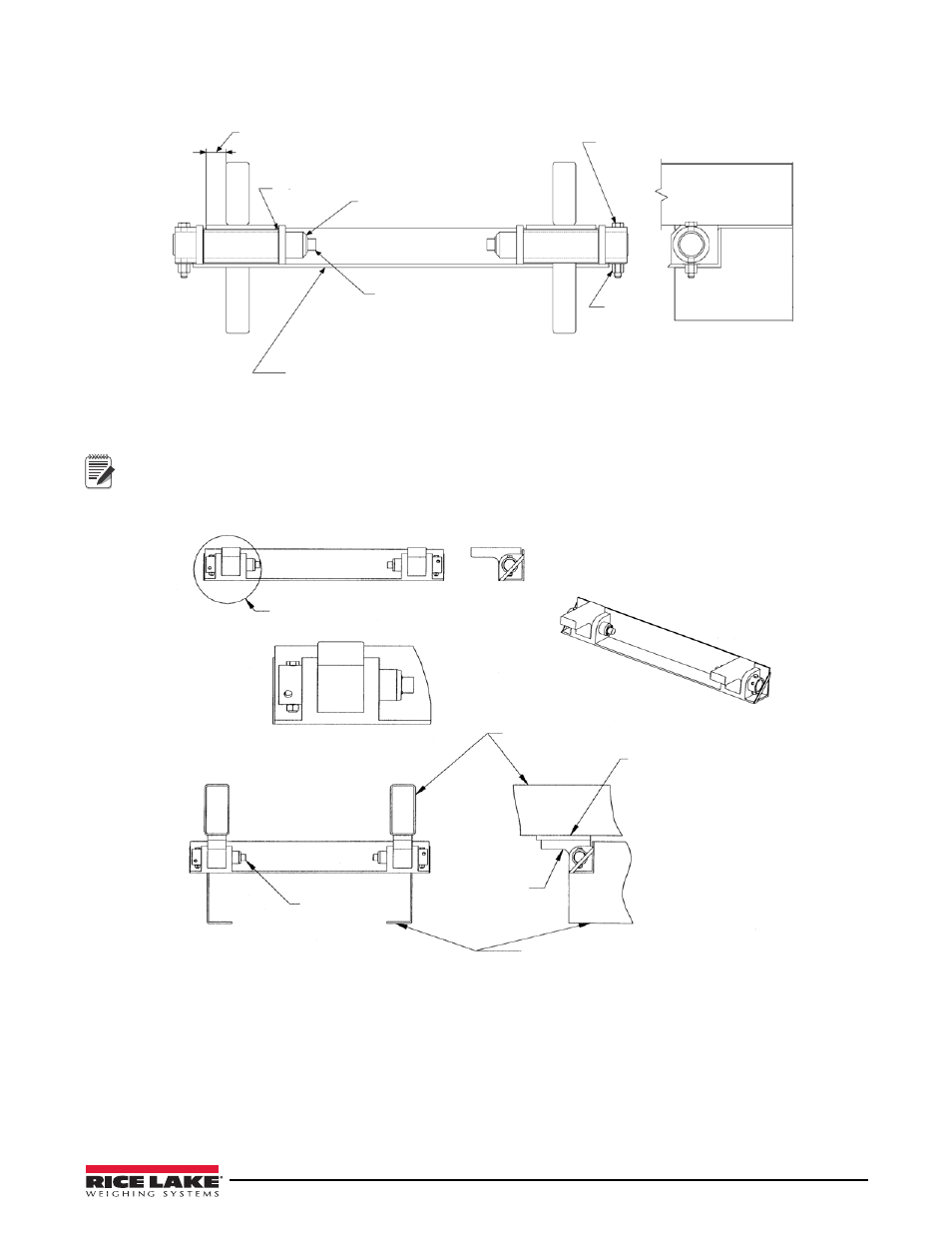
Truck bed frame approximately 1 1/4 inches
from the end of the rocker plate
Allow .06 to .12 between cheek
plates and rocker tube. Typical
Up Notation
Connectors Inboard
3 x 4 x 1/4 angle, length as necessary to provide
1/4 minimum weld prep out board of cheek plates
Locknut
Typical
1/2 bolt - grade 5 minimum
Typical
Figure 4-33. Typical Rear Hinge Pin Installation
See Detail
Pin Detail
Detail
Pin Detail
Body Long Sill
Add .75” or 1” thick shim
to elevate body runner
off chassis for live weigh
Collar
Pin Connectors
Face Inwards
Chassis Frame Railes
application
Note
HINGE RISER: Add 0.75" or 1" thick shim plate to elevate body runners off chassis if the installation involves
frame mount load cells with hinge pins for "live weigh" system kits, as shown in Figure 4-34.
Figure 4-34. Hinge Riser
4.6.2
Hinge Bar and Lift Cylinder Pin
Hinge Bar
Once installed, the rear pivot hinge bar must pass through the chassis and pivot plate bushings without binding or
pre-loading. See “Hinge Bar Installation Drawing” on page 64