3 technical specifications, 2 underbody load cell mounts, Technical specifications – Rice Lake Combination System - Precision Loads On-Board Weighing Systems User Manual
Page 20
16
Precision Loads On-Board Weighing Installation & Service Manual
4.1.3
Technical Specifications
Table 4-3. Air Pressure Transducer Technical Specifications
Sensor, Rated Capacity
250 psi (17 bar)
Safe Overload
2 times rated pressure
Sensor Material
17-4 PH Stainless Steel
Temperature Operating Range
-20 deg C to +80 deg C
Pressure Connection
Female ¼ NPT
Electrical Connection
4-pin male, molded nylon, MIL-spec equivalent, non-corrosive
Enclosure Sealing
Encapsulation
Enclosure Material
6061-T6 Anodized Aluminum Block
4.2
Underbody Load Cell Mounts
Load cell models typically used for underbody mounting are the PL9000-11 (light duty agriculture bodies only),
the PL9000-14 low profile bending beam, the PL9000-14.4 and the PL9000-16 heavy duty shear beams, the
PL9000-22 bending beam, and the PL9000-26 shear beam for high capacity applications. See “Underbody Load
Cell Chassis and Body Brackets Drawings” on page 65 for mounting bracket drawings. This section of the manual
refers specifically to the mounting of PL9000-14.4 load cells. Refer to load cell dimensional drawings in “Load
Cell Assemblies and General Specifications” on page 4 for information on bolt centers and sizes for load cell
models for underbody mounting.
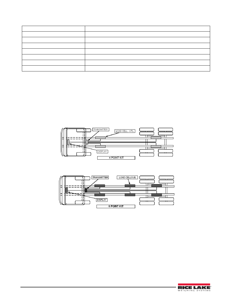
Figure 4-7. 4 Point Underbody Load Cell Kit
Figure 4-8. 6 Point Underbody Load Cell Kit
Before Getting Started
• Review Section 2.0 on page 3 to ensure you have all the tools required.
• Review “Stress Concentrations and Frame Reinforcing” on page 22.
• Rice Lake Weighing Systems recommends that trucks and trailers be thoroughly cleaned prior to retrofit
installations.
• Ensure that all load cells are properly spaced with respect to chassis and body length. Typical maximum
spacing between load cell centerlines is in the approximate range of 100 inches (254 cm) for PL9000-14,
PL9000-14.4, and PL9000-16 load cells, and 144 inches (365 cm) for PL9000-22 and PL9000-26 load cells.
This calculation must also take into consideration the type and strength of the underbody runner or subframe,
and the type of loads being supported. See “Stress Concentrations and Frame Reinforcing” on page 22.
Decisions on load cell spacing must be made by the install of the scale system.
• Ensure that the rated dynamic capacity of the load cell being used is appropriate for the specific vehicle and
loading practices involved. If in doubt concerning loading capacities, check with the vehicle owner.