6 spi connector (j21), Spi connector (j21) – Kontron KTA75-FLEX User Manual
Page 35
KTD-N0861-B
Page 27
Pin Connectors
KTA75/Flex Users Guide
KTA70M/mITX Users Guide
7.6
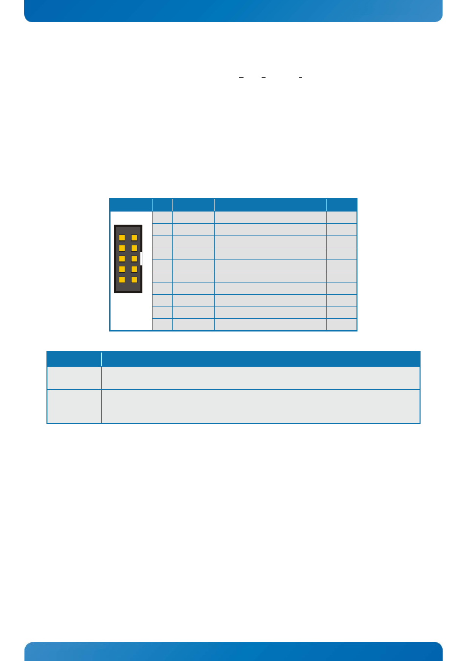
SPI Connector (J21)
The KTA75 provides one synchronous full duplex SPI (Serial Peripheral Interface) Bus in a 10 pin header
connector. The connector is type Pinrex 512-90-10GBE5 or similar.
Two things should be considered:
1.
An onboard SPI
TM
flash coexists on the same interface lines. You must disable this component with a
3.3V power connection to the ADDIN signal (e.g. a short circuit jumper between pin 2 and 4).
2.
The four SPI
TM
lines are protected with an additional bus driver and the ISOLATE# signal controls the
output enable pin. For normal operation this signal should be high.
Header
Pin
Signal
Description
Type
1
SPI_CLK
SPI clock
O-3.3
2
3.3V
Power +3.3V
PWR
3
SPI_CS#
SPI slave select, active low
O-3.3
4
ADDIN
Disable onboard SPI flash
I-3.3
5
RSVD
Reserved (10k pullup to 3.3V)
PWR
6
N.C.
Not connected
NC
7
SPI_MOSI SPI master output, Slave Input IO-3.3
8
ISOLATE#
Disable the SPI interface
I-3.3
9
SPI_MISO SPI master input, Slave Output IO-3.3
10
GND
Ground
PWR
Signal
Further description
SB3V3
3.3V Standby Voltage power line. Normally output power, but when Motherboard is turned
off then the on-board SPI Flash can be 3.3V power sourced via this pin.
ISOLATE#
The ISOLATE# input, active low, is normally NC, but must be connected to GND when
loading SPI flash. Power Supply to the Motherboard must be turned off when loading SPI
flash. The pull up resistor is connected via diode to 5VSB.
1