5 connector signal definitions, Connector signal definitions, 5connector signal definitions – Kontron KTA75-FLEX User Manual
Page 22: Kta75/flex users guide kta70m/mitx users guide
KTD-N0861-B
Page 14
Connector Signal Definition
KTA75/Flex Users Guide
KTA70M/mITX Users Guide
5
Connector Signal Definitions
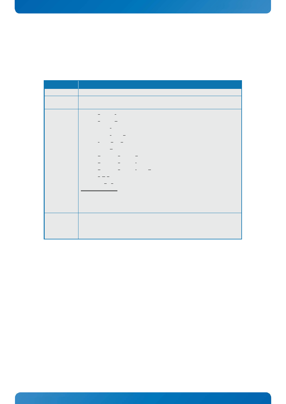
The following sections provide pin definitions and detailed description of all onboard connectors.
The connector definitions follow the following notation:
Column Name
Description
Pin
Shows the pin numbers in the connector.
Signal
The mnemonic name of the signal at the current pin. The notation “#” states that the signal
is active low.
Type
AI:
Analogue Input
AO:
Analogue Output
I:
Digital Input
IO:
Digital Input / Output
IOD:
Input / Open Drain output
O:
Digital Output
DSO:
Differential Signaling Output with complementary signals on two paired wires
DSI:
Differential Signaling Input with complementary signals on two paired wires
DSIO:
Differential Signaling Input / Output (combined DSO and DSI)
PWR:
PoWeR supply or ground reference pins
NC:
Pin Not Connected
Additional notations:
-5.0
+5.0V signal voltage level, e.g. I-5.0
-3.3
+3.3V signal voltage level, e.g. O-3.3
-1.8
+1.8V signal voltage level, e.g. IO-1.8
Ioh/Iol
Ioh: Typical current in mA flowing out of an output pin through a grounded load while the
output voltage has high level.
Iol: Typical current in mA flowing into an output pin from a VCC connected load while the
output voltage has low level.
The abbreviation tbd is used for specifications which are not available yet or which are not sufficiently
specified by the component vendors.