Compaq GS160 User Manual
Page 23
GS160/320 System Overview
2-5
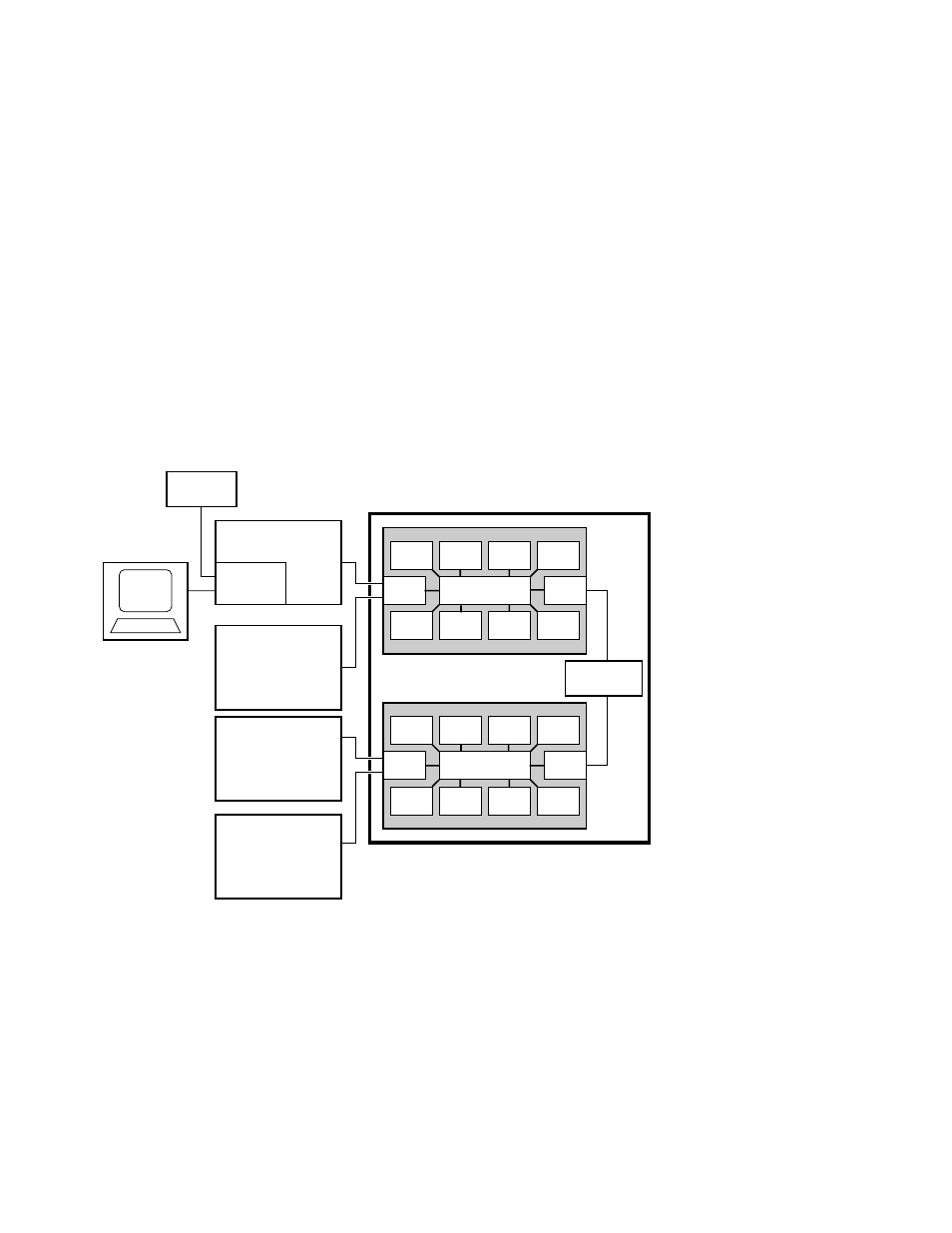
The switch on the backplane connects the CPU modules, memory modules, I/O
riser modules, and global port. In an 8-P system, the global ports connect the
QBBs to the distribution board. In a 16-P or a 32-P system, the global ports
connect the QBBs to the hierarchical switch.
Figure 2–3 System Box Block Diagram (8-Processor System)
Modem
Operator
Console
PCI Box
Standard
I/O SCM
PCI Box
System Box
CPU
MEM
I/O
GP
CPU
CPU
CPU
Switch
MEM
MEM
MEM
Distribution
Board
CPU
MEM
I/O
GP
CPU
CPU
CPU
Switch
MEM
MEM
MEM
PCI Box
PCI Box
PK-0601-98
This manual is related to the following products:
See also other documents in the category Compaq Computers:
- SR1602HM (2 pages)
- PROLIANT ML370 (152 pages)
- 228399-373 (73 pages)
- DA-10832 (20 pages)
- N1020V (219 pages)
- 1500 (204 pages)
- ProLiant DL585 G2 (46 pages)
- 277958-001 (74 pages)
- SR1010Z (1 page)
- DESKTOP 330 (20 pages)
- AERO 2100 (192 pages)
- DESKPRO 1000 (99 pages)
- Deskpro EN Series (31 pages)
- DL380 G2 (40 pages)
- 7000 (2 pages)
- 281862-002 (140 pages)
- 4000S (196 pages)
- EN Series (1 page)
- Presario PC (16 pages)
- Presario (96 pages)
- GS320 (290 pages)
- M700 (30 pages)
- 6000 (142 pages)
- 8000 (70 pages)
- 8000 (158 pages)
- Presario 7000 Series Internet PCQuick 470004-759 (1 page)
- AA-RHGWC-TE (362 pages)
- DS20 (82 pages)
- AP230 (31 pages)
- PROLIANT ML350 (89 pages)
- Professional Workstation AP200 (163 pages)
- Presario SR1610NX (2 pages)
- M300 (21 pages)
- EVO WORKSTATION W8000 (36 pages)
- S0000 (2 pages)
- DL580 (28 pages)
- 4-1 DA-10021-01-001 (20 pages)
- 160 (34 pages)
- Presario 6000 Series (2 pages)
- 505B (32 pages)
- Presario MyMovieSTUDIO (16 pages)
- Evo D510 e-pc (35 pages)
- Presario 7360 (214 pages)
- 4103TH (73 pages)