2 system box architecture – Compaq GS160 User Manual
Page 22
2-4
AlphaServer GS80/160/320 User's Guide
2.2
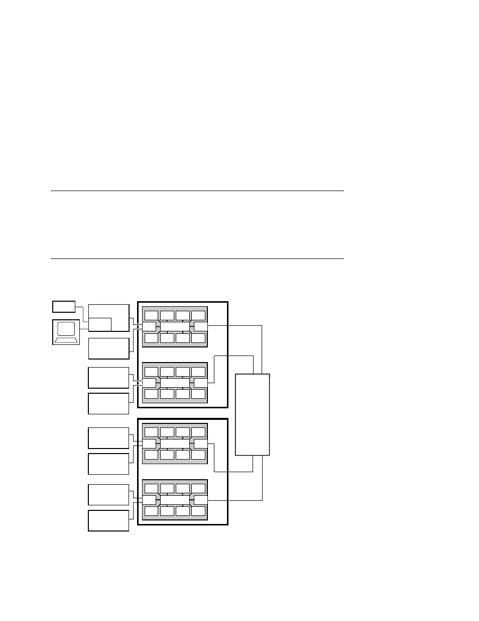
System Box Architecture
The system box houses two quad building blocks (QBBs). Each QBB
has a backplane with a switch interconnect that supports up to four
CPU modules, four memory modules, two power modules, two I/O riser
modules, and a global port. Figure 2–2 shows two system boxes
connected by the hierarchical switch. Figure 2–3 shows one system box
and the distribution board.
Figure 2–2 System Box Block Diagram (16-Processor System)
Operator
Console
PCI Box
Standard
I/O SCM
PCI Box
System Box 1
CPU
MEM
I/O
GP
CPU CPU CPU
Switch
MEM
MEM
MEM
CPU
MEM
I/O
GP
CPU CPU CPU
Switch
MEM
MEM
MEM
PCI Box
PCI Box
PCI Box
PCI Box
PCI Box
PCI Box
Modem
PK-0623-98
System Box 2
Hierarchical
Switch
CPU
MEM
I/O
GP
CPU CPU CPU
Switch
MEM
MEM
MEM
CPU
MEM
I/O
GP
CPU CPU CPU
Switch
MEM
MEM
MEM