Elecraft KAT100 User Manual
Page 32
32
Normal ATU Operation (AUTO Mode)
For normal operation, set the A T U menu entry to A U T O .
Hold
T U N E
to start auto-tune. Power will be decreased to 2 W (basic
K2) or 20 W (K2/100) if set above these levels. Power and SWR will
be displayed on the LCD during tune-up (e.g. 2 0 1 . 5 - 1 ). The SWR
portion of the display may flash occasionally if you're using high
power. SWR will also be shown on the KAT100's SWR LEDs.
The ATU itself will terminate
T U N E
after 1-5 seconds.
The ATU's L and C settings are stored in EEPROM, then recalled
instantly when you change bands or antennas. If you move
significantly off frequency, you may need to retune in order to keep
SWR low (especially at high power). The SWR LEDs on the KAT100
are activated during transmit to alert you to SWR changes.
Important ATU Operating Tips
• If the KAT100 uses a separate power supply from the
transceiver, the KAT100 supply must be turned on first.
• Erratic behavior of either the KAT100 or K2 may be observed
during auto-tune if excessive RF gets into the cables or circuitry. If
this happens at high power, reduce power to 10 watts or less for
auto-tune purposes. See Troubleshooting for other suggestions.
• Holding
T U N E
+
D I S P L A Y
overrides the tune-mode power limit
(2 watts for a basic K2, 20 watts for the K2/100), and temporarily
suspends A U T O mode. This is useful when you want to check
power output with the present L and C settings.
• A very low SWR is not necessary for good antenna performance,
but it will allow operation of the K2/100 at maximum power
output (see Antenna Considerations).
• If you tap
D I S P L A Y
to show the voltage/current display, then hold
T U N E
, you'll see the K2's transmit-mode voltage and current drain,
not power output and SWR. The tune-mode power limit will be
overridden, and the ATU's L and C settings will not change.
• The ATU menu entry can display current values of L and C,
network type, and other data. See ATU Menu Settings at right.
• Sometimes a slightly lower SWR can be found by repeating
T U N E
.
Bypassing the Matching Network (CAL mode)
You can bypass the matching network by setting the A T U menu entry
to C A L . This sets the L and C values in the matching network to
zero. However, there will still be considerable stray reactance present
within the ATU. This stray reactance may de-tune any antenna or
dummy load connected to the ATU's antenna jacks.
As an alternative to C A L , you can tune up the ATU into a 50-ohm
dummy load on each band using A U T O mode. This will cancel out the
tuner's stray reactance. After tuning up on all bands, put the ATU into
SWR (x . x - 1 ) mode, which will preserve the L and C settings.
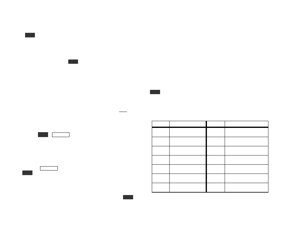
ATU Menu Settings
The table below lists all settings for the A T U menu entry. A U T O
mode is used most of the time. In this mode the ATU terminates
T U N E
automatically. The other modes are primarily used for
calibration and test. When you switch between C A L and A U T O
mode, you may hear a few relays switching, since in C A L mode, L and
C are set to 0. You'll also hear relays switch if you select the L 0 - L 8 ,
C 0 - C 8 , or N 1 - N 2 modes (see Troubleshooting).
Mode
Description
Mode
Description
C A L
Bypass (L/C = 0)
E x x x
0-199 = error code;
see Troubleshooting
A U T O Auto-tune mode
I N I T
Resets all L/C to 0 on
next power-up
x . x - 1
Auto-tune SWR
(present band/ant.)
F x . x x
KAT100 firmware
revision, e.g. F1.03
L x x . x
Inductance, µH
(present band/ant.)
L 0 - L 8
Individual inductor
selection
C x . x x Capacitance, nF
(present band/ant.)
C 0 - C 8
Individual capacitor
selection
N E T x
1=Cin, 2=Cout
(present band/ant.)
N 1
Selects Cin network;
L/C set to 0
T x x x
Combinations tried
(last auto-tune)
N 2
Selects Cout network;
L/C set to 0