Elecraft KAT100 User Manual
Page 22
22
Unwrap the front panel piece. Slide it over the LEDs on the
Front Panel board, then secure it to the 2-D fasteners on the bottom
of the RF board using two 4-40 x 3/16 [4.7 mm] screws (black).
Unwrap the side panels, and lay them on soft cloth with the
painted side down. The sides that are oversprayed (lightly painted)
should be facing up.
Sand or scrape away the overspray in the area of all four
mounting holes on both side panels. Be careful not to nick or sand too
close to the edge of the panel.
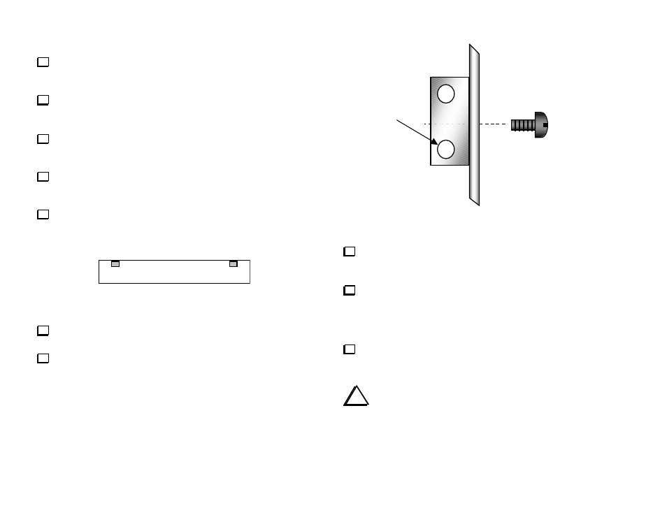
Place 2-D fasteners on the inside surface of the side panels at the
two locations shown in Figure 15. The panels are symmetrical, so
either edge can be considered the top.
Secure each 2-D fastener to the side panel using one 4-40 x 3/16"
[4.7 mm] screw (black). The fasteners must be oriented as shown
in the detail drawing, Figure 16.
Figure 15
Attach the side panels to 2-D fasteners already installed on the
RF board. Use one 4-40 x 3/16" [4.7 mm] screw (black) per fastener.
Secure the side panels to top surfaces of the front and rear panels.
Use one 4-40 x 3/16" [4.7 mm] screw (black) per fastener.
Holes offset
away from
panel
Figure 16
Unwrap the bottom cover piece, which can be distinguished from
the top cover by the presence of mounting holes for a tilt stand and
rubber feet. It is painted on both sides.
If you have purchased a tilt-stand kit for use with the KAT100,
install the stand and front/rear feet now, following the instructions
supplied. Otherwise, install the four self-adhesive, low-profile rubber
feet supplied with the KAT100-1. Position them near the corners of
the bottom cover.
Install the bottom cover. Secure it to the RF board in four places
using 4-40 x 3/16" [4.7 mm] screws (black).
i
Continue with K2 Firmware Installation on page 24.