Elecraft KAT100 User Manual
Page 12
12
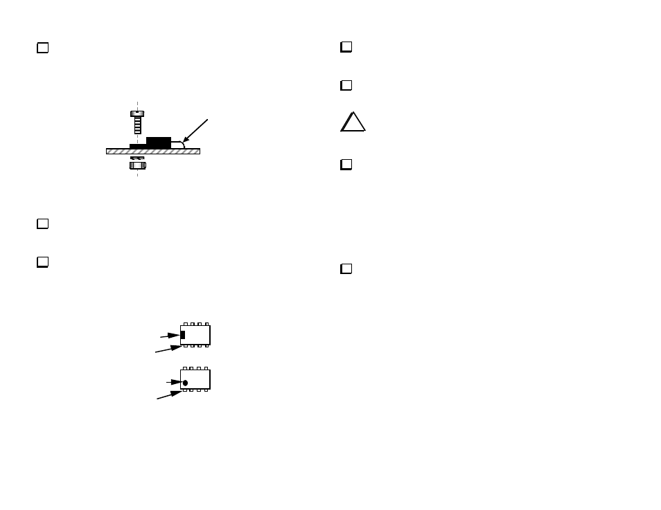
Locate voltage regulator U8 (78M05 or 7805). Bend the leads of
U8 to match its component outline (see Figure 4). Form the leads
around the shaft of a small screwdriver to create smooth rather than
sharp bends.
Use smooth bend
Figure 4
Insert U8's leads into the proper holes. Secure U8 with a 4-40 x
5/16" (8 mm) machine screw (zinc plated, not black), #4 lock washer,
and 4-40 nut.
Solder all three leads. Trim the leads on the bottom side.
Note: The pin 1 end of ICs can be identified by a notch or dimple as
shown in Figure 5. This end must be oriented toward the notched end
of the component outline.
Pin 1
Notch
Pin 1
Dimple
Figure 5
Install U5 (LM358, 8 pins), which is located in the back-right
corner. A portion of the part number is printed on the board under the
IC ("358"). Do not solder yet.
Bend two opposite corner pins on the bottom side to hold the IC
in place. Solder all 8 pins (about 1 to 2 seconds per pin).
i
U2, 3, and 4 (TPIC6B595) are especially sensitive to
electrostatic discharge. Touch a grounded surface before
handling each of them.
Install the remaining ICs. Compare the part number on each IC to
the number printed on the board, and make sure that the pin 1 end is
oriented correctly.
__ U2, __ U3, and __ U4, TPIC6B595 (or similar number ending in "595")
__ U6, EL5146
Note: U7 is not used.
Remove the relays from their tube. If any of the pins are bent,
straighten them carefully using long-nose pliers.