Final assembly – Elecraft KAT100 User Manual
Page 19
19
Final Assembly
Straighten the leads of microcontroller IC U1 (PIC16F877) as
shown below. The rows of pins must be straight and parallel to each
other to establish the proper pin spacing. To straighten the pins, rest
one row of pins against a hard, flat surface. Press down gently on the
other row of pins and rock the IC forward to bend the pins into
position as shown below.
Straight
Flared
Figure 11
Insert U1 into its socket, with the notched or dimpled end of the
IC aligned with the notched end of its socket and outline. (The labeling
on the IC should be upside down with respect to the "KAT100 RF"
label at the left side of the board.)
Examine U1 closely. If any pins are bent, remove the IC and
straighten them. (To remove U1 from its socket, pry it up gently on
each end using a small flat-blade screwdriver.)
i
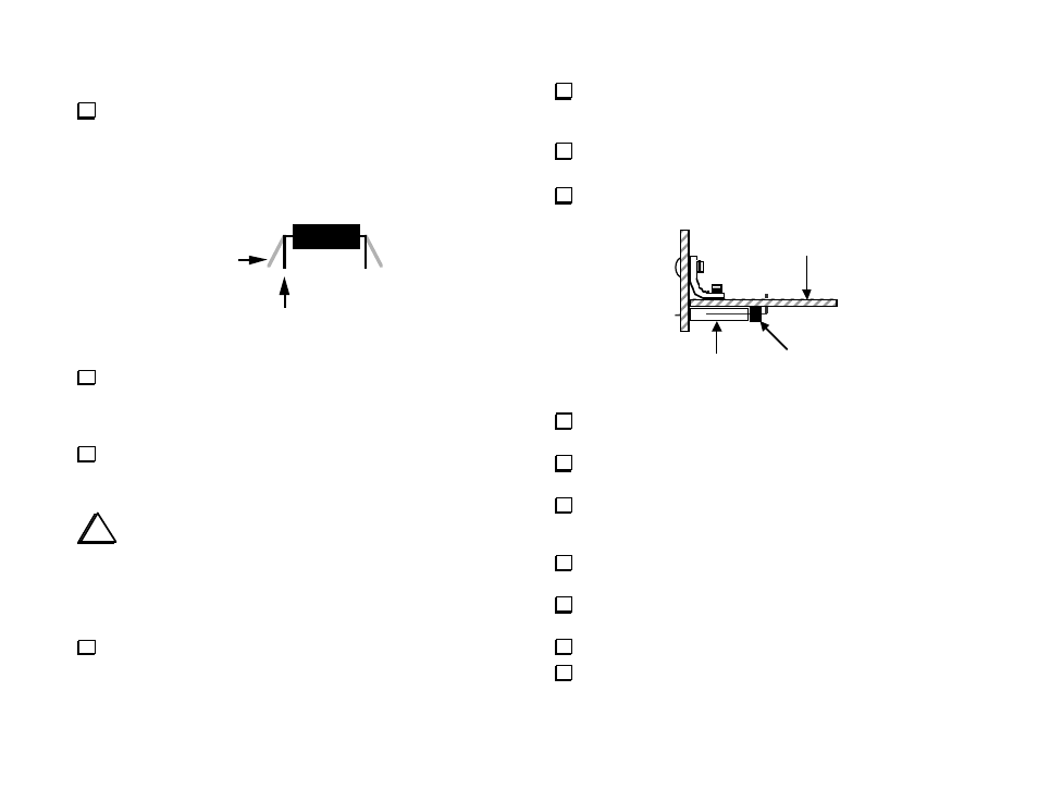
The right side view at Figure 12 shows how the Front
Panel and RF boards will be joined in the following steps.
J101 is a 12-pin female connector on the Front Panel board. P5 is a
12-pin right-angle male connector on the RF board. Also shown is one
of two L-brackets that secure the assembly and keep the Front Panel
board in a vertical position.
Locate the two small L-brackets. Identify the shorter side of the
"L", which will be attached to the RF board.
Place an L-bracket at one of the indicated locations at the front
edge the RF board. Align it with the component outline. If it's not
flush with the front edge, the short and long sides may be reversed.
Secure the L-bracket loosely to the RF board using a 4-40 x 3/16"
[4.7 mm] screw (black) and #4 lock washer.
Install the second L-bracket in the same way.
P5
Top of RF board
J101
Figure 12
Slide the 12-pin female connector (J101) onto the pins of the 12-
pin male connector (P5). There should be no gap between them.
Locate P5's outline on the bottom of the RF board. Insert P5's
right-angle pins into their holes. Do not solder yet.
Position the Front Panel board as shown above. The pins of J101
should be inserted into their holes, and the two L-brackets should be
aligned with their outlines on the back of the Front Panel board.
Secure the L-brackets loosely to the Front Panel using two 4-40 x
3/16" [4.7 mm] screws (black) and two #4 lock washers.
If the Front Panel is not aligned with the RF board along its front
edge, adjust the L-brackets positions.
Tighten the all four L-bracket screws.
Solder all pins of J101 and P5.