Elecraft KAT100 User Manual
Page 16
16
Locate the two dark gray (ferrite) toroid cores. The smaller of
the two (type FT37-43) has an outside diameter of 0.37" (9.5 mm).
This core will be used in the following steps.
RFC2 is wound on an FT37-43 core using 16 turns of #26 red
enamel wire (14", 36 cm). Wind and prepare this inductor in the same
manner as L1.
Install RFC2 vertically as indicated by its component outline near
relay K1.
i
Toroidal transformer T1 uses a bi-filar winding, which means
that two wires are wound on the core together. The wires will be
twisted together loosely before they're wound onto the core.
Cut two 11" (28 cm) lengths of #26 enamel wire, one red and
one green.
Twist the red and green wires together over their entire length.
The wires should cross over each other about every 1/2" (1 cm).
Wind 12 turns of the twisted wires onto the large ferrite core
(FT50-43). The turns should cover about 80-90% of the core, as
shown in Figure 9 (a white core was used to highlight the winding).
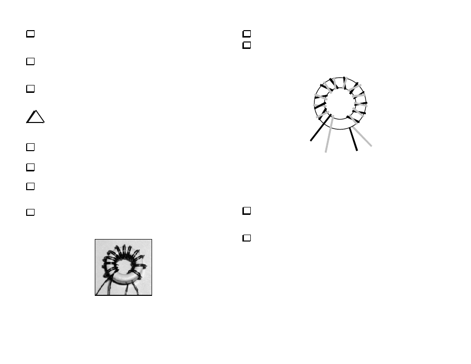
Separate T1’s leads as shown in Figure 10. The numbers on the
leads correspond to numbered pads on T1's PC board outline.
Figure 9
Strip and tin the leads of T1.
Using a magnifying glass, examine the red/green lead pairs to
make sure that the leads are not shorting together.
3
(RED)
2
(GRN)
1
(GRN)
4
(RED)
Figure 10
Install T1 vertically on the PC board as indicated by its outline
near the back edge of the board. Insert the red and green leads into
their numbered holes (see lead numbering above).
Verify continuity between the #1 and #4 pads of T1.