Elecraft KAT100 User Manual
Page 20
20
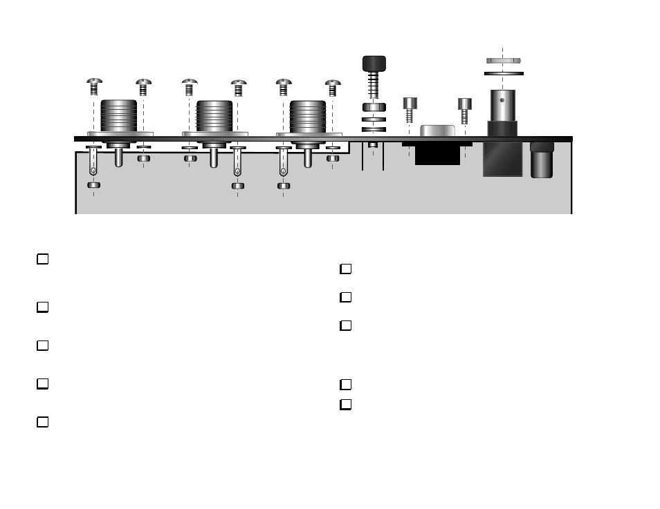
J6
J5
J4
E1
J3
J2
J1
Figure 13
Unwrap the rear panel piece, and place it with the labeling facing
away from you. Review Figure 13, which shows the vertical portion of
the panel, along with all of the panel- and PCB-mounted connectors.
Do not attach the rear panel to the RF board at this time.
Using the supplied sandpaper or a sharp tool, scrape away any
residual paint from around the hole for the ground terminal, E1. Do
this on the inside surface of the rear panel.
Sand or scrape residual paint from around at least one mounting
hole for each of the three SO239 connectors (J4, J5, and J6). Again,
this should be done on the inside surface.
Position J6 on the rear panel as shown. The connector's flange
should be on the outside of the panel. The center pin's solder cup
should be facing up to facilitate soldering in a later step.
Secure J6 with four 4-40 x 5/16" (8 mm) pan head screws, #4 split
lock washers, and 4-40 nuts. A solder lug takes the place of one lock
washer at the indicated corner, closest to the top edge of the rear
panel. Do not overtighten the hardware.
Position J5 and J4 on the rear panel in the same way as J6, with
the solder cups facing up.
Attach J5 and J4 to the rear panel using the same hardware. Note
the position of the solder lug on J5, which differs from J4 and J6.
Cut six lengths of #20 stranded hookup wire (vinyl insulated):
__ three black, 1.25" (3.2 cm) long
__ two red, 1.5" (4 cm) long
__ one red, 2.5" (6.3 cm) long.
Remove 1/4" (6 mm) of insulation from each end of all six wires.
Twist the strands of each wire tightly. Tin the wires using a small
amount of solder.