Elecraft KAT100 User Manual
Page 17
17
Uninstalled Components
Verify that these locations on the RF board are not filled:
Top side:
__ U1 (microcontroller, 16F877), should not be installed in its socket yet.
__ U7, front edge
__ W1-W6, front edge
__ W7, back edge
__ J7, right front corner
__ P7, right side, near L2
Top side, KAT100-1 only:
__ P6, __ P3, __ P4 (all along the right edge)
Bottom side:
__ R15
__ P1
__ P2
__ P5
P5 will be installed in the next section. The other uninstalled
components are reserved for future use.
Visual Inspection
i
Nearly all problems with kits are caused by poorly-
soldered component leads or incorrectly-installed components.
You can locate and correct most assembly errors ahead of time
with a simple visual inspection.
Using a magnifying glass, examine the bottom of the PC board
closely for all of the following: cold solder joints (dull rather than
shiny appearance), solder bridges, and leads that are not soldered. Re-
heat any suspect joints.
Using the parts placement drawing at the end of the appendix,
re-check the orientation of all __ Diodes, __ Transistors, __ ICs.
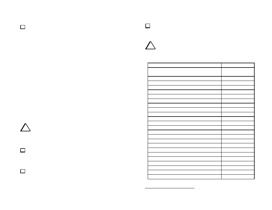
Resistance Checks
Make the resistance measurements listed below, touching the
DMM's (+) and (-) leads to the indicated points. The schematic may be
helpful in troubleshooting any incorrect readings.
i
The symbol
>
means greater than. Your DMM may indicate
infinite resistance (all digits flashing) for readings in the table that
include this symbol. Other readings should be +/- 10 %.
KAT100 Test Points (+, -)
Resistance
Between pins 2 and 5 of relays K1-K18
(on bottom of board, marked)
380-450 ohms
U8 (voltage regulator) "12V" pin, ground
1-30 k
U8 (voltage regulator) "5V" pin, ground
1-30 k
U2 (6B595) pin 2, ground
1-30 k
U2 (6B595) pin 3, ground
> 100 k
U2 (6B595) pin 9, ground
< 2 ohms
U2 (6B595) pin 12, ground
> 100 k
U2 (6B595) pin 13, ground
> 100 k
U2 (6B595) pin 18, ground
> 1 k
U6 (EL5146) pin 2, ground
1-30 k
U6 (EL5146) pin 3, ground
> 1 k
U6 (EL5146) pin 6, ground
> 1 k
U6 (EL5146) pin 7, ground
1-30 k
U6 (EL5146) pin 8, ground
> 100 k
U5 (LM358) pin 1, ground
> 100 k
U5 (LM358) pin 2, ground
> 100 k
U5 (LM358) pin 3, ground
45-55 k
U5 (LM358) pin 5, ground
45-55 k
U5 (LM358) pin 6, ground
> 100 k
U5 (LM358) pin 7, ground
> 100 k
D3 (1N5817) cathode
2
, ground
> 100 k
D3 (1N5817) anode, ground
> 100 k
D4 (1N5817) cathode, ground
> 100 k
D4 (1N5817) anode, ground
> 100 k
2
The banded end is the cathode.