Elecraft KAT100 User Manual
Page 14
14
i
In the next two steps, the leads of L1 will be stripped
and tinned. Toroid leads must be prepared correctly to
maintain reliability at the high voltages and currents seen by
the tuner.
There are three commonly-used methods to remove the enamel
coating from the leads: (1) heat-stripping, (2) burning/sanding, or (3)
scraping with a sharp tool. These methods are covered below.
(1) To heat-strip the enamel wire:
• Place a small amount of solder (a "blob") on the end of your
soldering iron
• Insert the clipped end of the wire into the hot solder. If the iron is
hot enough, you should see the insulation bubble and begin to
vaporize after 4 to 6 seconds.
• Add more solder and feed more of the wire into it as the enamel
melts. Continue tinning the wire up to the edge of the core. Then
slowly pull the wire out of the solder.
• If any enamel remains on the lead, scrape it away using your
thumbnail or a sharp tool.
(2) The insulation can be burned off by heating it with a butane lighter
for a few seconds. Use sandpaper to remove the enamel residue.
(3) You can scrape the insulation off using a razor blade or other sharp
tool. Avoid nicking the wire.
Strip the leads of L1 as described above. Remove the enamel from
the leads up to the edge of the core (see Figure 6).
Tin L1's leads with fresh solder. If the solder on the leads looks
dull or is not adhering very well, remove any residual enamel and re-tin
the lead.
Install L1 flat on the board as shown by its component outline
near relays K1 and K2. Do not solder yet.
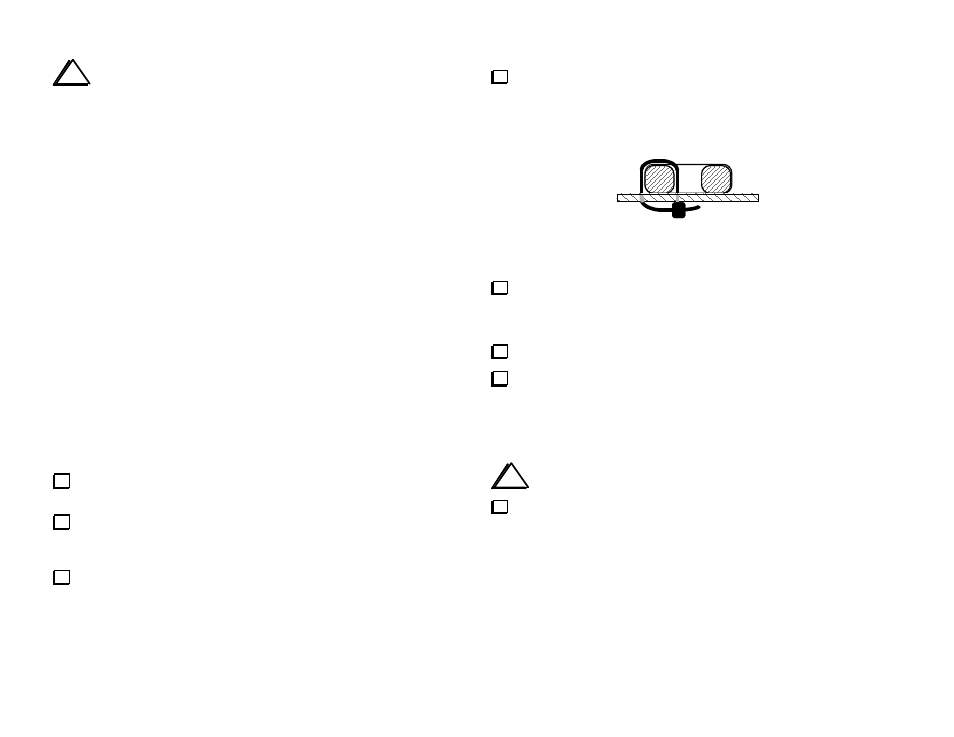
Secure L1 to the PC board using a cable tie. Two holes are
provided for this purpose, one inside the core and one outside. The
cable tie should be installed such that its "head" (thick end) ends up on
the bottom side, pressed tightly against the board (Figure 7).
Figure 7
Using a ruler, make sure that the head of the cable tie does not
extend more than 0.25" (6 mm) below the bottom of the board. This
would prevent proper installation of the bottom cover.
Trim off excess cable tie length.
Solder the leads of L1. When soldering, make sure that the solder
binds well to the leads. If the lead appears to be an "island" in a
pool of solder, it is not making good contact; remove the toroid
and prepare the leads as described above. (For further
information, look for "Soldering Tips" on our web site.)
i
Do not apply adhesives or fixatives of any kind to toroids.
Using your DMM on a low resistance scale, check for continuity
between L1's pads (not the leads) on the bottom of the board. If the
reading is over 1 ohm, re-strip the leads. Note: Your DMM probes will
have some residual resistance. Short them together to measure this
amount, and subtract it from your continuity readings.