Misc. control board changes – Elecraft K2ATOBKIT User Manual
Page 9
9
10. Misc. Control Board Changes
These changes improve various operating
characteristics of the K2, as explained in each of the
steps below. The parts for these changes are included
in K2ATOBKT.
Change R6 from 470 to 100 ohms (brown-black-
brown). (Improves auxBus noise immunity.)
Change R7 from 1.96 to 1.78k (brown-violet-
gray-brown). (Improves current measurement
accuracy.)
Change C12 from .001 to .0027 µF ("272").
(Improves auxBus noise immunity.)
Change C42 from .01 to 0.1 µF ("104").
(Stabilizes voltage display.)
Locate the trace on the top side of the board that
runs directly between resistors R8 and R9 (Figure 5).
Cut the trace. On the bottom side of the board, solder
an 820-ohm resistor (gray-red-brown) between the two
vias. You'll need to pre-trim the resistor's leads since it
isn't possible to cut the lead that falls between R8 and
R9. (Protects the microcontroller in the event that an
RS232 signal is accidentally connected to the
VRFDET line via the KIO2's or KPA100's AUX I/O
connector. Designated R12 on the Rev. B Control
board.)
R8 R9
Cut
R12 (on back)
Figure 5
If you have an older K2 (Rev XC or A), C31 may
be 0.1 µF ("104"). Change C31 to .047 µF ("473").
(Improves CW keying envelope shape.)
Sidetone Modification
These optional changes provide a more pleasant-
sounding sidetone.
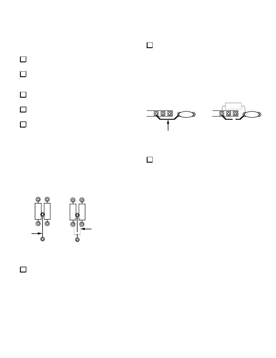
Locate capacitor C24 (.0027 µF), which is on the
right side of the Control board between RP7 and RP3.
As shown in Figure 6, cut the trace on the top side of
the board between C24 and pin 6 of RP7. On the
bottom side of the board, solder a 47 k resistor (yellow-
violet-orange) between these two pads. (Reduces
digital switching noise in the sidetone; designated R11
on the Rev. B Control board.)
C24
Cut
RP7
C24
RP7
R11 (on back)
Figure 6
Locate RP5, the 10-pin, 470-ohm RPACK at the
right side of the board. Solder an 82-mH shielded
inductor ("823") on the bottom of the Control board
between pins 7 and 10 of RP5. The leads of the
inductor should be formed such that the body can be
folded down flat against the PC board. (Designated L1
on the Rev. B board. Creates a low-frequency resonant
tank in conjunction with C33, greatly attenuating
harmonics of the sidetone. The resonant frequency is
approximately 400 Hz, but the Q is quite low, so
sidetone frequencies from 400-800 can still be used
effectively.)
RS-232 and Sidetone Source (KIO2/KPA100)
If either a KIO2 or KPA100 option is installed in the
Rev. A or XC K2, the builder must make a few
additional changes to the Control board. These changes
are fully documented in the KIO2 and KPA100
manuals. (The sidetone generation is re-routed from
pin 25 of the microcontroller, U6, to pin 4 of the quad
D-to-A converter, U8. This allows pin 25 of U6 to be
used for full-duplex RS232 communications.)
There is no need to make these changes until you add a
KIO2 or KPA100. In a later step, you'll set up your
K2's configuration based on whether or not you have at
some point installed either of these options.