K2atobkt mod kit inventory – Elecraft K2ATOBKIT User Manual
Page 2
2
K2ATOBKT Mod Kit Inventory
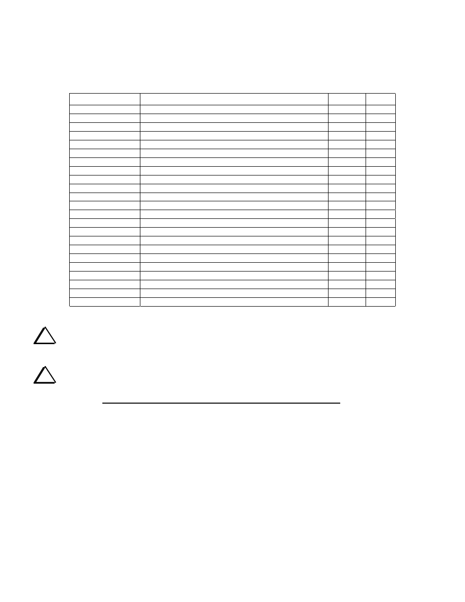
The parts supplied with K2ATOBKT mod kit are listed below. Other mod kits referenced in Table 1 include their own
parts lists.
Ref.
Description
Part
Qty
RF-C33
Capacitor, 2 pF ("2") or 2.2 pF ("2r2")
E530047
1
RF-C68
Capacitor, 10 pF
E530006
1
RF-C28,C29
Capacitor, 12 pF
E530058
2
RF-C
PLL
Capacitor, 68 pF
E530007
1
RF-C174
Capacitor, 82 pF
E530038
1
RF-C30,C36
Capacitor, 470 pF ("471")
E530004
2
RF-C91
Capacitor, .001 µF ("102")
E530001
1
CTRL-C12
Capacitor, .0027 µF ("272")
E530055
1
RF-C
RF
, CTRL-C31
Capacitor, .047 µF ("473")
E530025
2
CTRL-C42
Capacitor, 0.1 µF ("104")
E530011
1
RF-D10
Diode, ultra low-drop Shottky, 95SQ015
E560009
1
RF-R50
Resistor, 1.5 ohms, 1/2 watt (brown-green-gold)
E500025
1
RF-R64,CTRL-R6
Resistor, 100 ohms, 1/4 watt (brown-black-brown)
E500010
2
RF-R1, R2
Resistor, 220 ohms, 1/4 watt (red-red-brown)
E500002
2
CTRL-R12
Resistor, 820 ohms, 1/4 watt (gray-red-brown)
E500001
1
CTRL-R7
Resistor, 1.78 k, 1/4 watt, 1% (brown-violet-gray-brown)
E500026
1
RF-R
REFA
, R
REFB
Resistor, 10 k, 1/4 watt (brown-black-orange)
E500015
2
RF-R11
Resistor, 47 k, 1/4 watt (yellow-violet-orange)
E500067
1
RF-R18
Resistor, 1 M, 1/4 watt (brown-black-green)
E500024
1
RF-RFC11
Toroid, 20 turns #26 enamel on FT37-43 core
E680003
1
RF-RFC15
RF choke, miniature, 100 µH (brown-black-brown)
E690013
1
CTRL-L1
Inductor, shielded, 82 mH ("823", dark gray, cylindrical)
E690015
1
Misc.
Enamel wire, #26, red (for RFC11)
E760002
3 ft.
i
Caution: Some parts in the K2 can be damaged by static discharge. While making modifications, use an
anti-static wrist strap. Alternatively, you can touch a grounded, unpainted metal surface (do this often).
i
Updating the K2 to revision B involves a considerable amount of component removal. You will need a
full-size, hand-operated vacuum desoldering tool. The Edsyn model AS196 Anti-Static Solder Sucker ($25), is
an excellent choice. Before removing a component, straighten its leads on the solder side (use a small tool while
heating the solder joint). Next, clean out the holes using the desoldering tool. Finally, pull the component out,
being very careful not to damage pads, plated-through holes, or traces on the top or bottom sides of the board.