Firmware check and parameter save – Elecraft K2ATOBKIT User Manual
Page 3
3
1. Firmware Check and Parameter Save
Determine what revision of firmware you have by
turning the K2 on while pressing and holding any
switch. You'll see a display such as: 2 . 0 3 d 1 . 0 7 .
The number on the left is the firmware revision of the
main microcontroller, U6 on the Control board. The
other number is the firmware revision for the I/O
controller (IOC), U1 on the RF board. Record both of
the numbers here: K2 _______ IOC _______.
i
If your K2 firmware revision is older than
2 . 0 0 A , you'll need to install new firmware after
making all desired hardware changes. You may need to
install a new IOC in addition to the main micro-
controller. This will be explained later.
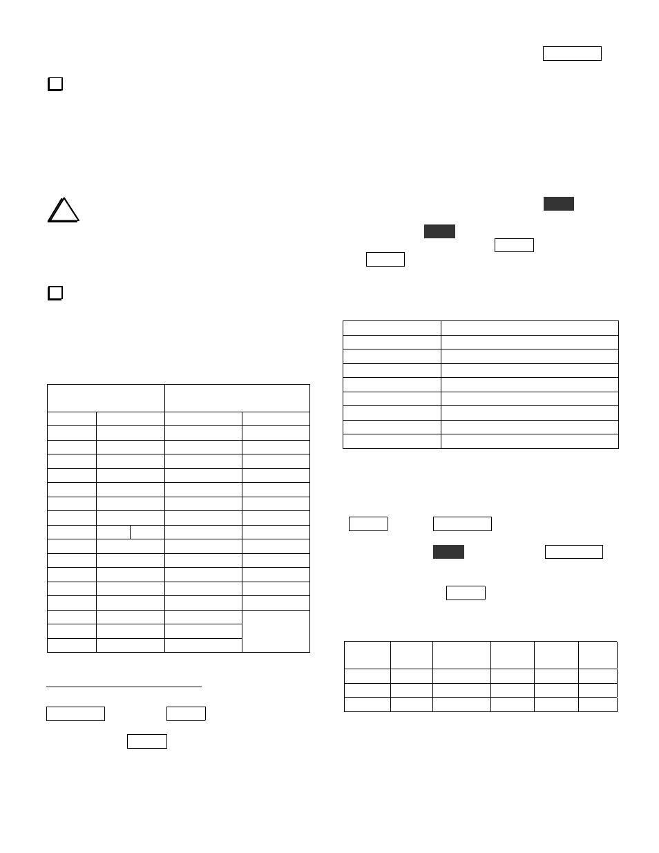
Whether or not you plan to install new firmware,
you should record your present configuration settings
in Tables 2 - 5. The BFO frequencies (Table 5) will be
needed if you make the Temperature Stability changes.
Table 2. Menu Parameters
Primary Menu
Secondary Menu
(Rev. 2.00 up
1
)
Entry
Param.
Entry
Param.
ST L
SLCH
ST P
RATES
T-R
DOT
RPT
FPLY
INP
PORT
IAB
SPLT
SSBA
Po28
SSBC
2
SSBC
SSBCr
RTTY
LCD
RTC
GRPH
RIT
OPT
ACC
ATU
AT2/D19
3
RANT
PA
CAL
Table 3
TRN1
PF1
TRN2
PF2
TRN3
Table 4
1
To switch between the
P R I
and
S E C
menus, tap
D I S P L A Y
after tapping
M E N U
.
2
If RTTY is set to
O N
(Rev 2.00 up), and
r
mode has
been selected with
M O D E
, the
S S B C
menu entry
changes to
S S B C r
. Record both settings if applicable.
3
If you have revision 2.03 or later firmware, the name of
this menu entry is
D 1 9
. Otherwise it is
A T 2
(which was
never used).
Supplemental Menu Parameters: The D I S P L A Y
switch is used to access additional parameters when
editing certain menu entries. These include sidetone
source (S T L entry), 8R Hold mode (T - R entry),
Auto-Detect mode (I N P entry), and Fan mode (P A
entry, secondary menu). These will be set up
appropriately during new firmware installation (page
10) and do not need to be recorded here.
CAL Settings (Table 3): To access CAL settings, use
the primary menu to scroll to C A L , hold
E D I T
to edit
the parameter, select a CAL function with the VFO
knob, then hold
E D I T
again to activate the function.
After recording the setting, tap M E N U to exit, then
tap M E N U again and access the next CAL function in
the same manner.
Table 3. C A L Settings
CAL Function
Parameter
OFF
n/a
FCTR
n/a
CUR
TPA
n/a (stored by KPA100)
S LO
S HI
PLL
n/a (CAL PLL will be done later)
FIL
Table 5
Transverter Band Displays (Table 4): You'll only
need to record these settings if you use the transverter
bands. To access transverter band display settings, tap
M E N U , then tap D I S P L A Y to switch to the
secondary menu, then scroll to the desired T R N x
menu entry. Hold
E D I T
to access it. Tap D I S P L A Y
to cycle through the five parameters for each
transverter band display. To select the next transverter
band setup, first tap M E N U to return to scroll mode.
Table 4. T R N x Band Displays (Rev 2.00 up)
Xvtr #
On
/Off
RF
IF
OFS
OUT
TRN1
TRN2
TRN3
(see next page for Table 5)